
Installation Instruction

(continued)
W10337809C
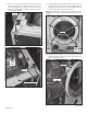
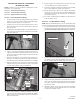
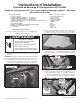
8. Attach vent tube sub-assembly to the 187 mm (7.40”) long
vent tube within dryer as shown in Figure 26.
9. Assure the positioning of the bottom exhaust vent assembly
then securely tighten the clamps. See Figure 26.
10. Bottom venting of your dryer is now complete. Reassemble
dryer in reverse order as the dryer was disassembled refer-
encing this instruction sheet assuring proper assembly and
wire lead connections.
11. Proceed to “Completing Dryer Installation” section at the end
of this instruction sheet.
Section 2 - Left Side Exhaust Venting
NOTE: Allow for a minimum clearance of 10” from wall to dryer side
panel if venting exhaust downward after exiting side panel of dryer.
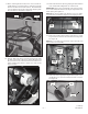
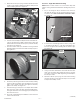
1. As you are facing the dryer, review the lower section of the left
side panel. If two (2) knockout features are present remove
the MOST REARWARD KNOCKOUT ONLY. See Figure 27.
figure 26
— 6 —
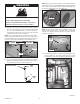
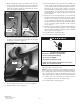
figure 25
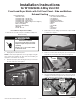
VENTING PROCEDURE IS CATEGORIZED
IN THREE SECTIONS
NOTE: Determine your new vent direction and follow the section
that applies to your application.
Section 1 – Bottom Exhaust Venting
Section 2 – Left Side Exhaust Venting
Section 3 – Right Side Exhaust Venting
Section 1 - Bottom Exhaust Venting
1. Position the dryer into its operating position in the room and
measure its rear corner location from the back wall and side
wall. Record these dimensions for future use.
2. Using two (2) corner posts from the shipping carton or other
protective material on the floor beside the dryer, gently lay
dryer on left side.
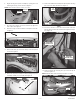
3. Using either a 1/8” drill bit and drill or a cold chisel and ham-
mer, remove the six (6) knockout retaining tabs around the
edge. See Figure 25.
4. Using a cold chisel and hammer around the knockout hole
edge, work around the edge until the knockout is removed.
Use a file to remove the small edge burrs generated by the
knockout procedure.
5. Reposition the dryer into its operating position using the di-
mensions recorded in step 2 above. Using the exhaust hole
in the bottom panel as a template, mark the floor accordingly.
6. Attach the 187 mm (7.40”) long vent to the blower housing
using the 3/8” long screw removed in step 20 of “Procedure
for Dryer Disassembly” section. See Figure 26.
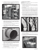
2. To remove the most rearward left side knockout, use either a
1/8” drill bit or a cold chisel and hammer. Remove the six(6)
knockout retaining tabs around the edge. See Figure 28.
figure 28
7. Create sub-assembly by combining the 86 mm ( 3.40”) long
vent tube , the elbow and two clamps included in kit. Slightly
tighten clamps to hold assembly together but yet allow for
movement at this time.
figure 27
3. Using a cold chisel and hammer around the knockout hole
edge, work around the edge until the knockout is removed.
Use a file to remove the small edge burrs generated by the
knockout procedure.
4. Attach the 187 mm (7.40”) long vent to the blower housing
using the 3/8” long screw removed in step 20 of “Procedure
for Dryer Disassembly” section.