
Installation Instruction

— 8 —
W10337809C
(continued)
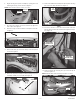
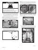
figure 34
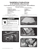
5. Assemble the 305 mm (12.0”) long vent tube and elbow from
kit together using clamp included in kit. Tighten clamp to hold
sub assembly together. See Figure 33.
6. Feed this vent tube sub-assembly into the dryer and out the
right side panel exhaust hole. Use clamp included with kit,
slide it onto the elbow and press the elbow onto the 187 mm
(7.40”) vent tube. See Figure 33.
7. Assure the positioning of the exhaust vent assembly and
securely tighten both clamps. See Figure 33.
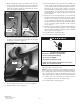
8. From the outside of the dryer, install the vent ring included
with kit by sliding over exhaust vent tube and snap into place.
See Figure 34.
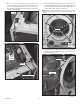
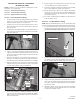
figure 35
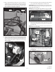
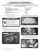
Completing Dryer Installation
IMPORTANT: Take special note of specific areas listed below
assuring proper re-assembly of dryer.
1. Reassemble dryer in reverse order as the dryer was disas-
sembled referencing previous instruction photographs and
following the steps below.
2. When reinstalling the drum, see Figure 17 for correct drum
front direction.
3. When reattaching drum belt, verify belt grooves are toward
the drum outer surface. Lift up on the idler pulley arm and loop
the belt into position as shown in Figure 16. Slowly release
the idler arm putting tension on the belt. Slightly lift up on
drum front and slowly rotate to verify belt is seated correctly.
4. Swing the front bulkhead to the dryer front and reattach the
two (2) wire harness clips to the front of the front bulkhead.
When re-hanging the front bulkhead to the dryer, make sure
the wire harness is not getting pinched and the mid-section
of the front bulkhead edge is behind the side panel edge.
See Figure 35 as well as Figure 13.
5. Seat the front bulkhead rollers up under the drum lip and turn
the drum to verify they are seated. Reattach four (4) screws
in the corners, Figure 13.
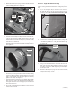
6. At the bottom of the front bulkhead is a lower protective flap.
Verify flap is laying above the blower sensor connectors as
shown in Figure 36.
figure 36
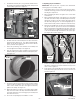
figure 33
9. Assure the positioning of the exhaust vent assembly, making
sure the positive stop bump on the 305 mm (12.0”) long vent
tube is on the outside of the dryer. See Figure 34. Securely
tighten both clamps. See Figure 33.
10. Right side venting of your dryer is now complete. Reassemble
dryer in reverse order as the dryer was disassembled refer-
encing this instruction sheet assuring proper assembly and
wire lead connections.
11. Proceed to “Completing Dryer Installation” section.