
User Manual


4
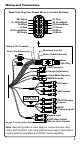
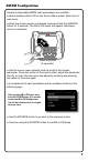
Wiring and Connections
Wire Color Location Function
Black Plug Pin A
Negative Chassis Ground (-)
Blue Plug Pin B
Amp Turn-On (+12v Output)
Green Plug Pin C
Left Rear Speaker (+)
Green/Black Plug Pin D
Left Rear Speaker (-)
Gray/Black Plug Pin E
Right Front Speaker (+)
Gray Plug Pin F
Right Front Speaker (-)
Purple Plug Pin G
Right Rear Speaker (+)
Purple/Black Plug Pin H
Right Rear Speaker (-)
Red Plug Pin J
+12 volt Accessory
White Plug Pin K
Left Front Speaker (+)
White/Black Plug Pin L
Left Front Speaker (-)
Yellow Plug Pin M
+12 volt Constant (>10a)
Purple/White Harness
Reverse Camera +12v Input
Orange Harness
+12 volt Illumination
Preamp Level Audio Connections
● Front and rear RCA preamp outputs are labeled as such. These are
intended to be connected to external ampliers, not included.
● Subwoofer RCA outputs (green RCAs) are mono and paralleled.
They are identical subwoofer audio signals. Their frequency range is
controlled by the low pass crossover and the subwoofer level control.
Both are found in SETTINGS. See Page 18. We recommend starting
with 100Hz for the low pass crossover point.
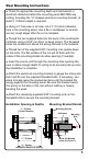
● The unit offers a zone control feature to balance sound levels
between different zones. The front and/or rear RCA outputs (using
external ampliers) are one zone. The source unit's built-in power is
the other zone. An example is a boat having separate volume control of
amplied wakeboard tower speakers versus cabin speakers positioned
closer to listeners using the unit's built-in power. Zone level control is
found in SETTINGS. See page 18. Subwoofer RCA outputs or speaker-
level outputs are unaffected by the zone level control. All work with the
main volume.
● We recommend wire-to-wire connections such as power, ground and
speaker wiring are soldered and protected with either heat shrink tubing
or high quality electrical tape.
● The main (yellow) power wire should be connected to a source with at
least 10 amps of additional current capability to support the unit.