Assembly Instructions Model: Jeep JL (Wrangler) & JT (Gladiator) Description: Front, Rear, Top Dash Speaker Install with Amplifier Part Number: MBQJ-STG6A-1 & MBQJ-STG6AH-1 Assembly Time: 120 Min (2-Hours) Before you beign, read thought these instructions and check that all parts are present. Please note that MB Quart cannot assume any responsibility for damage resulting from incorrect installation. Parts ListParts List No. Component Name Qty 1 6.5in Midbass Speaker Kit (JW1-116E) 2 2 6.
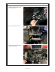
Dash Disassembly ● Unclip and remove panel below the steering column ● Remove (2) Phillips screws ● Unclip, unplug, and remove the climate control panel Page 2 of 33
Dash Disassembly ● Remove (2) Phillips screws securing the radio trim panel, then unclip and remove ● Remove (1) Phillips screw securing the front dash pad, carefully unclip and remove by pulling forward toward the front seats Page 3 of 33
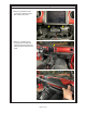
Dash Disassembly ● Carefully unclip the instrument panel shroud along the bottom and remove ● Unclip the lower steering column shroud and move toward steering wheel Page 4 of 33
Dash Disassembly ● Unclip and remove the panel on the side of the dash ● Remove (5) Phillips screws that are exposed ● Unclip kick panel cover Page 5 of 33
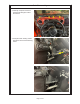
Dash Disassembly ● Remove (1) Phillips screw from lower left dash ● Remove (2) Phillips screws near steering column ● Remove (2) Phillips screws on the top of the left dash then unclip and disconnect wiring on back of light switch to remove panel from vehicle Page 6 of 33
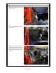
Lower Speaker Removal ● Remove (4) 10mm bolts below steering column.
Lower Speaker Removal ● Disconnect harness from the enclosure and module mounted on the back side, then remove from vehicle ● Remove the module from the OEM enclosure Page 8 of 33
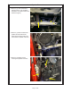
Dash Disassembly ● Install the module on the new enclosure using the OEM hardware ● On passenger side remove (4) Phillips screws Page 9 of 33
Dash Disassembly ● Unclip and remove the panel on the side of the dash ● Using a panel tool carefully remove the grab handle cover (starting on the left) Page 10 of 33
Dash Disassembly ● Remove (2) 10mm bolts securing the grab handle and set handle aside ● Unclip the airbag cover panel ● Remove (2) Phillips screws that have been exposed Page 11 of 33
Dash Disassembly ● Remove glove box by opening and lifting the upper tab and removing the latch on the left side ● Remove three Phillips screws that have been exposed ● Looking in the glovebox cavity up high, remove two 13mm bolts securing the back of the passenger side airbag Page 12 of 33
Dash Disassembly ● Carefully unclip the air bag.
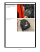
Dash Disassembly ● Remove (3) Phillips screws holding the passenger speaker enclosure, then disconnect wires and remove from vehicle Page 14 of 33
Upper Speaker Replacement ● If you are replacing the upper speakers as well, complete Steps 34 and 35 for driver and passenger side.
Upper Speaker Replacement ● Install new speaker enclosure and secure with (3) Phillips screws ● Connect the speaker enclosure to the wiring Note – If just replacing the pods, but not adding amplifiers, then you will connect to OEM plug, but if you are adding amplifiers, then you will connect to the new harness.
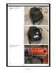
Upper Speaker Replacement ● Lifting the airbag slightly and install (5) Phillips screws ● Remove (2) Phillips screws, disconnect wiring and remove speaker from vehicle ● Carefully clip the airbag into place Page 17 of 33
Upper Speaker Replacement ● Looking in the glovebox cavity up high, install (2) 13mm bolts securing the back of the passenger side airbag ● Install (3) Phillips screws at bottom of glovebox opening ● Install glovebox by installing bottom hinge and pivoting up.
Upper Speaker Replacement ● Install (2) Phillips screw at the bottom of the passenger airbag ● Clip the airbag cover panel into place ● Install (2) 10mm bolts securing the grab handle Page 19 of 33
Upper Speaker Replacement ● Slide ears on cover into slot and snap grab handle cover into place ● Install (5) Phillips screws on the side of dash ● Clip the passenger side dash cover into place Page 20 of 33
Upper Speaker Replacement ● Install (4) Phillips screws on the top of the air bag ● Connect the speaker enclosure to the wiring Note – If just replacing the pods, but not adding amplifiers, then you will connect to OEM plug, but if you are adding amplifiers, then you will connect to the new harness.
Lower Speaker Install ● Install (3) Phillips screw to secure the enclosure ● Install (1) 8mm bolt below the speaker ● Install (4) 10mm bolts below steering column.
Dash Reassembly ● Connect and install driver side dash ● Install (2) Phillips screws on the top of the left dash ● Install (1) Phillips screw from lower left dash Page 23 of 33
Dash Reassembly ● Install (1) Phillips screw from lower left dash ● Clip kick panel cover into place ● Install (5) Phillips screws on driver side of dash Page 24 of 33
Dash Re-assembly ● Clip the dash side panel into place ● Clip the steering column shroud into place ● Install (2) Phillips screws on shroud Page 25 of 33
Dash Reassembly ● Clip the instrument panel shroud into place ● Install (4) Phillips screws on the driver side securing instrument panel shroud ● Clip top of dash into place Page 26 of 33
Dash Reassembly ● Install (1) Phillips screw ● Clip the radio shroud into place and install (2) Phillips screws ● Connect the wiring Page 27 of 33
Dash Re-assembly ● Connect the wiring and clip the climate control panel into place ● Install and clip in place the lower steering column cover ● If you are replacing the top dash speakers, make sure to connect the wires that you passed from the lower pod to the speaker Page 28 of 33
Upper Speaker Replacement ● Install speaker with (2) Phillips screws ● Clip top dash grill into place Page 29 of 33
Rear Speaker Installation ● Remove four 5mm Allen bolts to remove the OEM Grill ● Remove and disconnect (4) T30 Torx screws from the port and (5) T20 Torx screws from both speakers ● Apply painter tape to the soundbar, then hold the 6x9 speaker mounting plate up and mark the speaker opening Page 30 of 33
Rear Speaker Installation ● Remove 6x9 mounting plate to show roughly the cutting and using a rotary cutting tool, cut a hole similar to the picture on the right BE VERY CAREFUL not to cut the OEM wiring as this will be used with the 6x9 speaker ● Mount the 6x9 metal plate to the soundbar with (8) Phillips screws Page 31 of 33
Rear Speaker Installation ● Connect the harness adapter to the OEM plug and connect to the 6x9, then mount the 6x9 to the mounting plate using (4) M4 Screws and washers ● Mount the new soundbar grill for the 6x9 with the OEM 5mm bolts ● Reference Wiring/Amplifer install manual for installing the NA2-400.2RC amplifiers.
FCC Notification This equipment has been tested and found to comply with the limits for a Class B digital device, pursuant to part 15 of the FCC Rules. These limits are designed to provide reasonable protection against harmful interference in a mobile installation. This equipment generates uses and can radiate radio frequency energy. If not installed and used in accordance with the instructions, this equipment may cause harmful interference to radio communications.
Wiring/Amplifier Installation Guide Model: Jeep JL (Wrangler) & JT (Gladiator) Description: Wiring/Amplifier Install Part Number: MBQJ-ACC-1 & MBQJ-ACC-1AH Assembly Time: 120 Minutes (2 Hours) Before you beign, read thought these instructions and check that all parts are present. Please note that MB Quart cannot assume any responsibility for damage resulting from incorrect installation. Parts List No. Component Name Qty 1 NA2-400.2RC 2 2 NA2-400.
Disassembly Step 1 ● To get to this point will be Step 1 to 4 from the speaker installation Remove (5) Phillips screws from center dash/screen area Step 2 ● Unclip lower center console and move toward rear of vehicle Step 3 ● Disconnect large main harness connector on back of radio screen. Then connect the PAC Audio T-Harness into the radio and the OEM connector into the T-Harness.
Disassembly Step 4 ● Route T-Harness pigtail from radio pocket to lower console behind metal brace Step 5 ● Continue routing pigtail harness toward glovebox opening (this will be where the main control box will be hidden) Step 6 ● Unclip passenger kick panel cover Page 3 of 22
Disassembly Step 7 ● Disconnect passenger door harness, door strap, and 10mm nut that has been exposed Step 8 ● Unclip passenger sill cover, it is easiest starting at the rear of the door opening and moving forward, once unclipped remove from vehicle Step 9 ● With passenger seat slid all the way back remove (2) T-50 Torx bolts Page 4 of 22
Disassembly Step 10 ● Slide passenger seat forward and remove (2) T-50 Torx bolts from the rear Note Do not remove seat from vehicle Step 11 ● Remove front two roof sections (which will aid in soundbar disassembly to follow) and refer to your Jeep owner manual on removal of top Step 12 ● Remove (4) T25 Torx screws from the passenger side upper roll cage cover and set aside Page 5 of 22
Disassembly Step 13 ● Unclip and disconnect the dome light Step 14 ● Remove (3) T-25 Torx screws from the front edge of the soundbar cover and then unclip and remove set aside Step 15 ● Remove the fir tree clip, then gently unclip the T-panel, (you will NOT be removing from the vehicle just gaining enough space to pass soundbar wiring behind) Page 6 of 22
Disassembly Step 16 ● Unclip rear door sill panel first two clips by moving towards the center of the vehicle Step 17 ● Unclip the two covers on B-Pillar sill panel Step 18 ● Unclip and remove B-Pillar sill panel Page 7 of 22
Subwoofer Install if applicable Step 19 ● If no subwoofer being install skip Steps 19 to 22 Remove (4) 10mm bolts securing the under seat storage compartment, (may need to remove rubber insert to gain access to bolts) Step 20 ● Remove jack Page 8 of 22
Subwoofer Install if applicable Step 21 ● Cut a small hole in the carpet (as pictured) to pass the subwoofer extension harness through going toward the outside of the vehicle along door seal toward passenger seat area Step 22 ● Install jack Page 9 of 22
Wiring Install Step 23 ● Disconnect OEM connector from soundbar, and connect new harness, and then zip tie along OEM wiring moving down the B-Pillar to under the passenger seat Step 24 ● Clip the T-panel into place and install the first tree clip Page 10 of 22
Wiring Install Step 25 ● Clip soundbar cover into place and install (3) T-25 Torx screws on the front edge Step 26 ● Clip dome light back in place Step 27 ● Place passenger roll cage cover into position and install (4) T25 Torx screws Page 11 of 22
Wiring Install Step 28 ● Clip the B-Pillar panel back into place sliding under rear door seal panel Step 29 ● Clip (2) covers back on the B-Pillar seal panel Step 30 ● Clip rear door seal panel into the B-Pillar panel Page 12 of 22
Wiring Install & Assembly Step 31 ● Install front (2) roof sections and refer to your Jeep owner manual for installation of top Step 32 ● Pull back carpet along center console.
Wiring Install & Assembly Step 34 ● Connect the remote wire to the PAC Audio pigtail harness, then connect the interface box to the pigtail harness, (at this point the RCAs can be plugged in and reference the labels to connect properly) Step 35 ● Place the PAC Audio interface box (like pictured) Note – If you choose to use the included knob from PAC to control the subwoofer and door chime volume, then place somewhere easily accessible in the vehicle Step 36 ● Place amplifier power connections under passe
Wiring & Amplifier Install Step 37 ● Remove grommet Step 38 ● Using a utility knife, make a small cut Step 39 ● Pass the power wire through the grommet and to the underside of the vehicle, and then install the grommet back into its location Page 15 of 22
Wiring & Amplifier Install Step 40 ● Install the grommet back into its location Step 41 ● Under the vehicle zip tie the harness along the OEM wire channel should move forward into the fender area Step 42 ● Pass power wire up passenger fender near battery Note Pass a fish tape from top down to help pull wire up Page 16 of 22
Wiring & Amplifier Install Step 43 ● Crimp and heat the fuse butt connector by the battery Step 44 ● Remove 70A MAXI fuse and make connection to the battery with a 10mm socket Step 45 ● Place front speaker wire harness under passenger seat and route wires along OEM harness from under seat to door jam routing forward to kick area (zip tie all wires in this area to OEM wiring and now carpet can be put back into place) Page 17 of 22
Wiring Install & Assembly Step 46 ● Place amplifiers on mounting plate in order pictured ● Loosely start M4 screws mounting amplifiers, once all screws have been installed go back and tighten. SUBS Step 47 ● Tilting the passenger side seat forward, connect the power and speaker connections to the appropriate amplifiers.
Wiring Install & Assembly Step 49 ● Zip tie front speaker wires along OEM wires to pass up into the dash toward the passenger front speaker location Step 50 ● Reinstall passenger front door sill clipping into place Step 51 ● Connect passenger door harness, door strap and install 10mm nut Page 19 of 22
Wiring Install & Assembly Step 52 ● Clip passenger kick panel cover Step 53 ● Pass the driver side speaker wire along the glove box lower frame, behind glove box door gear, and into the center dash area Step 54 ● Continue routing the driver side speaker wire under the lower center dash wire to driver side Page 20 of 22
Wiring Install & Assembly Step 55 ● Continue passing driver speaker wire from center dash area to under steering column area and route wire along lower dash support behind bracing NOTE This connection will be connected to the new Drivers side speaker.
FCC Notification This equipment has been tested and found to comply with the limits for a Class B digital device, pursuant to part 15 of the FCC Rules. These limits are designed to provide reasonable protection against harmful interference in a mobile installation. This equipment generates uses and can radiate radio frequency energy. If not installed and used in accordance with the instructions, this equipment may cause harmful interference to radio communications.