PCIe-DIO24 Digital Input/Output User's Guide Document Revision 2 September 2014 © Copyright 2014
Your new Measurement Computing product comes with a fantastic extra — Management committed to your satisfaction! Thank you for choosing a Measurement Computing product—and congratulations! You own the finest, and you can now enjoy the protection of the most comprehensive warranties and unmatched phone tech support. It’s the embodiment of our mission: To provide data acquisition hardware and software that will save time and save money.
Table of Contents Preface About this User's Guide ....................................................................................................................... 4 Conventions in this user's guide ......................................................................................................................... 4 Where to find more information .........................................................................................................................
Preface About this User's Guide This user's guide describes the Measurement Computing PCIe-DIO24 data acquisition device and lists device specifications. Conventions in this user's guide For more information Text presented in a box signifies additional information related to the subject matter. Caution! Shaded caution statements present information to help you avoid injuring yourself and others, damaging your hardware, or losing your data.
Introducing the PCIe-DIO24 Chapter 1 Overview: PCIe-DIO24 features This manual explains how to install and use the PCIe-DIO24 board. The PCIe-DIO24 is a digital I/O board designed for the PCI Express (PCIe) bus. The PCIe-DIO24 provides 24 lines of digital I/O with selectable 3.3 V and 5 V logic levels. The 24 DIO lines are organized into three groups of 8-bits each (Port A, Port B, and Port C). Port C can be further divided into two four-bit ports (Port C-HI and Port C-LO).
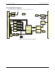
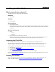
PCIe-DIO24 User's Guide Introducing the PCIe-DIO24 Functional block diagram PCIe-DIO24 functions are illustrated in the block diagram shown here. +12V +12V (pin 16) +V DIO (pin 18) +V DIO Regulated Fuse Protection Spare Fuse VDIO and 12V Fuse Protection 1.5V Regulator +V DIO (pin 20) 3.3V 3.3V Board Power +5 (VDD) 3.3V 5V Regulator 37-pin I/O Connector IRQ Enable 8 PORT A Buffering 8 PORT B Buffering PORT CL Buffering 4 PORT CH Buffering 4 3.3/5V PORT A Direction CTR 3.
Chapter 2 Installing the PCIe-DIO24 What comes with your shipment? The following items are shipped with the PCIe-DIO24: Hardware PCIe-DIO24 Software MCC DAQ CD Documentation MCC DAQ Quick Start This booklet provides an overview of the MCC DAQ software you received with the device, and includes information about installing the software. Please read this booklet completely before installing any software or hardware.
PCIe-DIO24 User's Guide Installing the PCIe-DIO24 Installing the hardware The PCIe-DIO24 is completely plug-and-play. Configuration is controlled by your system's BIOS. To install your board, follow the steps below. Install the MCC DAQ software before you install your board The driver needed to run your board is installed with the MCC DAQ software. Therefore, you need to install the MCC DAQ software before you install your board. Refer to the Quick Start Guide for instructions on installing the software.
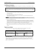
PCIe-DIO24 User's Guide Installing the PCIe-DIO24 +5V Logic level switch 3V +VDIO * GND PORT C7 PORT C6 PORT C5 PORT C4 PORT C3 PORT C2 PORT C1 PORT C0 PORT A7 PORT A6 PORT A5 PORT A4 PORT A3 PORT A2 PORT A1 PORT A0 20 21 22 23 24 25 26 27 28 29 30 31 32 33 34 35 36 37 1 2 3 4 5 6 7 8 9 10 11 12 13 14 15 16 17 18 19 IRQ INPUT IRQ ENABLE PORT B7 PORT B6 PORT B5 PORT B4 PORT B3 PORT B2 PORT B1 PORT B0 GND Open GND Open GND +12V* GND +VDIO* GND Figure 2.
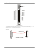
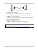
PCIe-DIO24 User's Guide Installing the PCIe-DIO24 1 19 1 20 37 19 20 37 Figure 4. C37FFS-x cable Field wiring and signal termination You can use the following MCC screw terminal boards and relay racks with the PCIe-DIO24 board using the C37FF-x or C37FFS-x cable: SCB-37 – 37-conductor, shielded signal connection/screw terminal box that provides two independent 37pin connections. CIO-MINI37 – 4 x 4, 37-pin screw terminal board.
Chapter 3 Functional Details 82C55 emulation The PCIe-DIO24 emulates the 82C55 Programmable Peripheral Interface (PPI) chip. Measurement Computing's Universal Library and Windows driver supports mode 0 only. Whenever the board is powered on or reset, all pins are set to high-impedance input. Based on standard TTL functionality, these inputs typically float high, and may have enough drive current to turn on external devices.
Chapter 4 Specifications All specifications are subject to change without notice. Typical for 25 °C unless otherwise specified. Digital input/output Table 1. Digital I/O specifications Parameter Specification Digital type Configuration 82C55 Emulation 2 banks of 8, 2 banks of 4, programmable by bank as input or output Ports A and B: 74HC245A Port C: 74HC126 Ports A and B: 74HC245A Port C: 74HC125 24 I/O Board silk screen reference: S1 – Default +5V 2.8 volts min @ -2.5 mA 0.3 volts max @ 2.5 mA 2.
PCIe-DIO24 User's Guide Specifications Environmental Table 3. Environmental specifications Parameter Specification Operating temperature range Storage temperature range Humidity 0 °C to 50 °C –20 °C to 70 °C 0% to 90% non-condensing Mechanical Table 4. Environmental specifications Parameter Specification Dimensions (L × W × H) 167.4 × 111.2 × 18.72 mm (6.60 × 4.38 × 0.74 in.) Bus Table 5. Bus specifications Parameter Specification Bus Type Bus Width PCI Express 1.
PCIe-DIO24 User's Guide Specifications Table 7.
Declaration of Conformity According to ISO/IEC 17050-1:2010 Manufacturer: Address: Measurement Computing Corporation 10 Commerce Way Suite 1008 Norton, MA 02766 USA Product Category: Date and Place of Issue: Electrical equipment for measurement, control and laboratory use.
Measurement Computing Corporation 10 Commerce Way Suite 1008 Norton, Massachusetts 02766 (508) 946-5100 Fax: (508) 946-9500 E-mail: info@mccdaq.com www.mccdaq.