
User`s guide


11
Chapter 3
Functional Details
82C55 emulation
The PCIe-DIO24 emulates the 82C55 Programmable Peripheral Interface (PPI) chip. Measurement
Computing's Universal Library and Windows driver supports mode 0 only.
Whenever the board is powered on or reset, all pins are set to high-impedance input. Based on standard TTL
functionality, these inputs typically float high, and may have enough drive current to turn on external devices.
Consequently, if you have output devices such as solid state relays, they may be switched on whenever the
computer is powered on or reset. To prevent unwanted switching, and to drive all outputs to a known state after
power on or reset, configure each port resistor with InstaCal.
Unconnected inputs float to the pull direction
Unconnected inputs will float in the pull direction that is configured for the port with InstaCal (either up/high or
down/low).
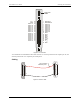
Replacing a fuse
The PCIe-DIO24 has two individual 0.375 amp slow blow fuses. One fuse is connected to the 12V output at pin
16, and is labeled
F7 on the board. The second fuse is connected to both +V
DIO
outputs at pin 18 and pin 20, and
is labeled
F6 on the board. A spare fuse is installed on the board at location F4. All fuses are secured to the
board with clips for convenient replacement.
A fuse will blow during operation if amperage exceeds 0.375 amp. If you need to replace a fuse, perform the
following procedure.
1. Hold the center of the blown fuse and pry it from the fuse holder clip.
2. Insert the replacement fuse into the fuse holder clip.
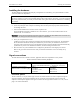
Fuse specifications
Refer to the information below to purchase additional fuses, if required:
Manufacturer: LittelFuse®
Type: 452 Series NANO
2®
Slo-Blo
®
Subminiature Surface Mount Fuse
Part number: 0452.375
0.375 amp, 125 volts, 1.2 Ω
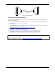
Logic level switch
Use switch S1 to set the logic level for either 3.3V or 5V (default). The switch is located above the I/O
connector (see Figure 2 on page 9).
Figure 5. Logic level select switch
3.3V
5V
S1