
User`s guide


5
Chapter 1
Introducing the PCIe-DIO24
Overview: PCIe-DIO24 features
This manual explains how to install and use the PCIe-DIO24 board. The PCIe-DIO24 is a digital I/O board
designed for the PCI Express (PCIe) bus.
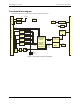
The PCIe-DIO24 provides 24 lines of digital I/O with selectable 3.3 V and 5 V logic levels. The 24 DIO lines
are organized into three groups of 8-bits each (Port A, Port B, and Port C). Port C can be further divided into
two four-bit ports (Port C-HI and Port C-LO). The direction of each port is independently configurable with
software for either input or output. Digital outputs are HC logic and can source and sink 2.5 mA.
The PCIe-DIO24 has a 10 k resistor network associated with each digital port. You can configure each port for
pull-up or pull-down with software. On power up and reset the configuration of each port is read from
EEPROM. The board is shipped with each port configured in the pull-up state.
The PCIe-DIO24 emulates the 82C55 Programmable Peripheral Interface (PPI) chip. Measurement
Computing's Universal Library and Windows driver supports mode 0 only.
Digital I/O lines are accessible through a 37-pin D-type connector. The board has two individual slow blow
fuses rated at 0.375 amp to protect the +V
DIO
and +12V outputs on the connector. One spare fuse is provided.
Software programs written with the Universal Library for the USB-DIO24/37, PCI-DIO24 and CIO-DIO24
devices are fully compatible with the PCIe-DIO24.
Power is provided by the PCI Express slot. The PCIe-DIO24 board is completely plug-and-play. All board
addresses are set by the board's plug-and-play software. Board configuration is controlled by your system's
BIOS.