
User`s guide


PCIe-DIO24 User's Guide Installing the PCIe-DIO24
8
Installing the hardware
The PCIe-DIO24 is completely plug-and-play. Configuration is controlled by your system's BIOS. To install
your board, follow the steps below.
Install the MCC DAQ software before you install your board
The driver needed to run your board is installed with the MCC DAQ software. Therefore, you need to install the
MCC DAQ software before you install your board. Refer to the Quick Start Guide for instructions on installing
the software.
1. Power off and unplug the computer, and remove the cover to expose the expansion slots.
2. Touch any metal part of the computer to discharge static electricity that may be present. Static electricity
can damage the board.
3. Insert the PCIe-DIO24 into an unused x1 PCIe expansion slot.
The PCIe-DIO24 is designed to install into an x1 slot. However, you can also install the board into an
unused x4, x8, or x16 PCIe slot.
Caution! Ensure that you install the board into a PCIe slot. Installing the PCIe-DIO24 into a non-PCIe slot
can damage both the board and the computer’s motherboard.
4. Close your computer and turn it on.
A dialog box opens as the system loads, indicating that new hardware has been detected. The information
file for this board should have already been loaded onto your PC when you installed the Measurement
Computing Data Acquisition Software CD supplied with your board, and should be detected automatically
by Windows. If you have not installed this software, cancel the dialog and install it now.
5. Run InstaCal to test your installation and to configure the pull direction of the digital port resistors.
Refer to the Quick Start Guide that came with your board for information on how to initially set up
InstaCal.
Signal connections
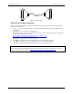
The table below lists the board I/O connector, applicable cables and compatible accessory boards.
Board connectors, cables, accessory equipment
Connector type 37-pin D-type
Compatible cables C37FF-x unshielded ribbon cable. x = length in feet. (see Figure 3)
C37FFS-x cable shielded round cable. x = length in feet. (see Figure 4)
Compatible accessory products
(with the C37FF-x or C37FFS-x cable)
SCB-37
CIO-MINI37
CIO-MINI37-VERT
CIO-ERB08
CIO-SERB08
CIO-ERB24
SSR-RACK08
SSR-RACK24
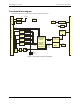
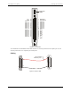
Connector pinout
The I/O connector is a 37-pin, male D-type connector accessible from the rear of the computer through the
expansion backplate. The signals available are direct connections to the digital I/O chips as well as the
computer's internal power supplies. The logic level switch sets the logic level for either 3.3V or 5V; refer to
page 11 for switch information.