
User`s guide


PCIe-DIO24 User's Guide Installing the PCIe-DIO24
9
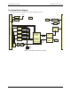
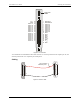
Figure 2. I/O connector
* The board has two individual slow blow fuses rated at 1 A. One fuse protects the 12V output at pin 16, and
one fuse protects both +V
DIO
outputs at pin 18 and pin 20.
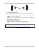
Cabling
Figure 3. C37FF-x cable
+V * 20
GND 21
PORT C7 22
PORT C6 23
PORT C5 24
PORT C4 25
PORT C3 26
PORT C2 27
PORT C1 28
PORT C0 29
PORT A7 30
PORT A6 31
PORT A5 32
PORT A4 33
PORT A3 34
PORT A2 35
PORT A1 36
PORT A0 37
DIO
1 IRQ INPUT
2 IRQ ENABLE
3 PORT B7
4 PORT B6
5 PORT B5
6 PORT B4
7 PORT B3
8 PORT B2
9 PORT B1
10 PORT B0
11 GND
12 Open
13 GND
14 Open
15 GND
16 +12V*
17 GND
18 +V *
19 GND
DIO
Logic level
switch
+5V
3V
20
1
37
19
20
1
37
19
The red stripe
identifies pin # 1