
Corporation Blower User Manual

-- 4 --
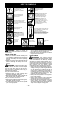
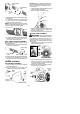
WHAT IS WHAT?
1. Throttle trigger 9. Upper blower tube
2. STOP switch 10. Lower blower tube
3. Primer button 11. High--speed nozzle
4. Choke lever 12. Elbow tube
5. Fuel cap 13. V acuum bag
6. Starter rope 14. Upper vacuum tube
7. Vacuum handle 15. Lower vacuum tube
8. Spark plug 16. Instruction manual
WHA T IS WHAT?
14
15
13
12
6
1
2
8
9
10
11
4
3
7
5
16
ASSEMBLY
CARTON CONTENTS
Check carton contents aga inst the following list.
S Blower
S Upper blower tube
S Lower blower tube
S High velocity nozzle
S Elbow tube
S Vacuum bag
S Upper vacuum tube
S Lower vacuum tube
S Screw for vacuum tube assembly
NOTE: It is normal for the fuel filter to rattle
in the empty fuel tank.
ASSEMBLY
WARNING: Stop engine and be sure
the impeller blades have stopped turning be-
fore opening the vacuum inlet door or at-
tempting to insert or remove the vacuum or
blower tubes. The rotating blades can cause
serious injury . Always disconnect the spark
plug before performing maintenance or ac-
cessing movable parts.
WARNING: If received assembled,
repeat all steps to ensure your unit is properly
assembled and all fasteners are secure. Fol-
low allsafety information in the manual and on
the unit.
D A standard screwdriver is required for as-
sembly.
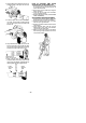
BLOWER ASSEMBLY
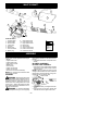
BLOWER TUBE ASSEMBLY
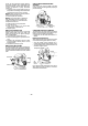
1. Align the rib on the upper blower tube with
the groove in the blower outlet; slide the
tube into place.
NOTE: The tube clamp bolt must be loose
enough to allow blower tube to be inserted in
blower outlet. Loosen the bolt by turning coun-
terclockwise (do not remo ve nuts).
Blower Outlet
Rib
Groove
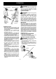
2. Secure the tube by turning the bolt clock-
wise.
3. Align the slots on the lower blower tube
with the tabs on the upper blower tube.