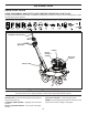
MC550 Operator's manual "This machine is approved by the EPA for E10 (10% ethanol) and lower fuel only. Do not use any fuel >E10 in this machine." 532439959 11.04.10 BAD Printed in the U.S.A.
SAFETY RULES Safe Operation Practices for Walk-Behind Powered Rotary Tillers TRAINING • • • • • Read the Owner’s Manual carefully. Be thoroughly familiar with the controls and the proper use of the equipment. Know how to stop the unit and disengage the controls quickly. Never allow children to operate the equipment. Never allow adults to operate the equipment without proper instruction. Keep the area of operation clear of all persons, particularly small children, and pets.
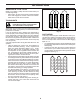
PRODUCT SPECIFICATIONS CUSTOMER RESPONSIBILITIES • • Read and observe the safety rules. Follow a regular schedule in maintaining, caring for and using your tiller. Follow instructions under “Maintenance” and “Storage” sections of this Manual. Gasoline Capacity: 0.9 Quarts (0,85 L) Unleaded Regular Oil (API-SG-SL): (Capacity: 20 oz./0.6L) SAE 10w-30(Above 32°F/0°C) SAE 5w-30(Below 32°F/0°C) • Spark Plug: (Gap: .030"/0.
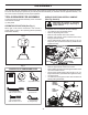
ASSEMBLY Your new tiller has been assembled at the factory with exception of those parts left unassembled for shipping purposes. To ensure safe and proper operation of your tiller all parts and hardware you assemble must be tightened securely. Use the correct tools as necessary ensure proper tightness. TOOLS REQUIRED FOR ASSEMBLY UNPACK CARTON & INSTALL HANDLE (See Fig. 2 and 3) A socket wrench set will make assembly easier. Standard wrench sizes are listed.
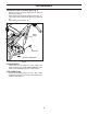
ASSEMBLY TO INSTALL DEPTH STAKE (See Fig. 4) • • • Remove screw(s) securing depth stake to skid and discard the screw(s). Slide depth stake down into transport arm track, lining up a hole in the depth stake with hole in transport arm. Install clevis pin and hairpin clip. DEPTH STAKE CLEVIS PIN HAIRPIN CLIP Fig. 4 TILLING WIDTH • Tilling width may be adjusted to better handle your tilling conditions (See “TINE ARRANGEMENT” in the Service and Adjustments section of this manual.
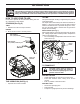
OPERATION KNOW YOUR TILLER READ THIS MANUAL AND SAFETY RULES BEFORE OPERATING YOUR TILLER. Compare the illustrations with your tiller to familiarize yourself with the location of various controls and adjustments. Save this manual for future reference. These symbols may appear on your Tiller or in literature supplied with the product. Learn and understand their meaning. FORWARD TINE CONTROL PRIMER RECOIL STARTER HANDLE THROTTLE CONTROL DEPTH STAKE Fig.
OPERATION The operation of any tiller can result in foreign objects thrown into the eyes, which can result in severe eye damage. Always wear safety glasses or eye shields before starting your tiller and while tilling. We recommend a wide vision safety mask for over spectacles or standard safety glasses. 00155 HOW TO USE YOUR TILLER TILLING The speed and depth of tilling is regulated by the position of the depth stake. The depth stake should always be below the wheels for digging.
OPERATION BEFORE STARTING ENGINE IMPORTANT: WHEN OPERATING IN TEMPERATURES BELOW 32°F(0°C), USE FRESH, CLEAN WINTER GRADE GASOLINE TO HELP ENSURE GOOD COLD WEATHER STARTING. IMPORTANT: BE VERY CAREFUL NOT TO ALLOW DIRT TO ENTER THE ENGINE WHEN CHECKING OR ADDING OIL OR FUEL. USE CLEAN OIL AND FUEL AND STORE IN APPROVED, CLEAN, COVERED CONTAINERS. USE CLEAN FILL FUNNELS.
OPERATION BREAKING IN YOUR TILLER Break-in your belt(s), pulleys and tine control before you actually begin tilling. • Start engine, tip tines off ground by pressing handles down and engage tine control to start tine rotation. Allow tines to rotate for five minutes. TILLING HINTS 3 4 CAUTION: Until you are accustomed to handling your tiller, start actual field use with throttle in slow position. 5 To help tiller move forward, lift up the handles slightly (thus lifting depth stake out of ground).
FILL IN DATES AS YOU COMPLETE REGULAR SERVICE BE FO MAINTENANCE SCHEDULE RE EA CH FIR US ST E 5H OU R EV S ER Y8 HO UR EV S ER Y2 5H OU EV RS ER OR Y5 0H AN NU O UR AN AL NU SO LY AL R LY AN NU AL LY MAINTENANCE SERVICE DATES Check Engine Oil Level Change Engine Oil 3 1,2 Oil Pivot Points Inspect Spark Arrester / Muffler Clean Air Cooling System 2 Clean Air Filter 2 Replace Air Filter Clean Area Around Muffler And Controls Replace Spark Plug 1 - Change more often when operating under a heavy lo
MAINTENANCE Disconnect spark plug wire before performing any maintenance (except carburetor adjustment) to prevent accidental starting of engine. Prevent fires! Keep the engine free of grass, leaves, spilled oil, or fuel. Remove fuel from tank before tipping unit for maintenance. Clean muffler area of all grass, dirt, and debris. Do not touch hot muffler or cylinder fins as contact may cause burns. ENGINE 3. Tip tiller on its side as shown and drain oil into a suitable container.
MAINTENANCE COOLING SYSTEM (See Fig. 15) SPARK PLUG Your engine is air cooled. For proper engine performance and long life keep your engine clean. • Remove blower housing and clean as necessary. • Keep cylinder fins free of dirt and chaff. TRANSMISSION Replace spark plugs at the beginning of each tilling season. Spark plug type and gap setting are shown in “PRODUCT SPECIFICATIONS” on page 3 of this manual. Your transmission is sealed and will not require lubrication unless serviced.
SERVICE AND ADJUSTMENTS CAUTION: Disconnect spark plug wire from spark plug and place wire where it cannot come into contact with plug. TILLER TO CHECK TINE OPERATION • TINE ARRANGEMENT • • Your outer tines can be assembled in several different ways to suit your tilling or cultivating needs. TO REMOVE CLUTCH HOUSING/ENGINE ASSEMBLY (SEE FIG. 19) CAUTION: Tines are sharp. Wear gloves or other protection when handling tines. • • NORMAL TILLING - 24" PATH (See Fig.
SERVICE AND ADJUSTMENTS TO REPLACE V-BELT (SEE Fig. 20 - 22) • • • • • • Clutch housing/engine assembly must be removed to service belt. See "TO REMOVE CLUTCH HOUSINGIENGINE ASSEMBLY" in this section of manual. Using pliers, remove cable spring and return spring from pivot bracket. Remove plastic snap-in plug from clutch housing. Using pliers, depress conduit fitting tabs and pull conduit fitting through hole in clutch housing. Pull cable spring and cable through snap-in plug hole in clutch housing.
STORAGE OTHER Immediately prepare your tiller for storage at the end of the season or if the unit will not be used for 30 days or more. • • WARNING: Never store the tiller with gasoline in the tank inside a building where fumes may reach an open flame or spark. Allow the engine to cool before storing in any enclosure. • • TILLER • • • • • Clean entire tiller (See “CLEANING” in the Maintenance section of this manual).
TROUBLESHOOTING PROBLEM CAUSE CORRECTION 1. 2. 3. 4. 5. Out of fuel. Engine not “CHOKED” properly. Engine flooded. Dirty air cleaner. Water in fuel. 1. 2. 3. 4. 5. 6. 7. Clogged fuel tank. Loose spark plug wire. 6. 7. 8. 9. Bad spark plug or improper gap. Carburetor out of adjustment. 8. 9. Fill fuel tank. See “TO START ENGINE” in the Operation section. Wait several minutes before attempting to start. Clean or replace air cleaner cartridge.
TILLER - - MODEL NUMBER MC550 (96083000301) DECALS 4 3 1 2 KEY PART NO. NO.
TILLER - - MODEL NUMBER MC550 (96083000301) ENGINE, TRANSMISSION, AND TINES 4 5 2 1 3 2 6 7 9 5 7 10 8 11 12 18 19 13 14 15 20 16 17 21 25 13 23 22 30 30 24 28 5 5 29 27 31 26 29 engine-transmission-tines_1 18
TILLER - - MODEL NUMBER MC550 (96083000301) ENGINE, TRANSMISSION, AND TINES KEY PART NO. NO.
TILLER - - MODEL NUMBER MC550 (96083000301) HANDLE, WHEEL, AND DEPTH STAKE 2 3 1 24 7 5 8 4 6 9 23 13 21 19 5 10 10 14 15 22 18 5 11 23 20 17 12 16 18 17 17 Handles-Wheels-Depth Stake_1_r1.
TILLER - - MODEL NUMBER MC550 (96083000301) HANDLE, WHEEL, AND DEPTH STAKE KEY PART NO. NO. DESCRIPTION 1 2 3 4 5 6 7 8 9 10 11 12 13 14 15 16 17 18 19 20 21 22 23 24 Console Tiller Handle Grip Handle Assembly Handle Column Bolt 5/16 - 18 x 2.50 Knob Wing Cable Asm. Retainer Ring Pin Pivot Handle Lower Plug Snap In Weldment Transport Arm Clip Hairpin Stake Depth Pin Clevis Bolt 3/8 - 16 x 1-1/4 Screw Hex Head 3/8 - 16 x 2.5 Nut Lock Flg 3/8 - 16 unc Bolt 5/16 - 18 x 4.5 Wheel Washer 17/32 x 7/8 x 16 Ga.
LIMITED WARRANTY The Manufacturer warrants to the original consumer purchaser that this product as manufactured is free from defects in materials and workmanship. For a period of one (1) years from date of purchase by the original consumer purchaser, we will repair or replace, at our option, without charge for parts or labor incurred in replacing parts, any part which we find to be defective due to materials or workmanship. This Warranty is subject to the following limitations and exclusions. 1.
GARANTÍA LIMITADO El fabricante le garantiza al comprador consumidor original que este producto no tendrá defectos en los materiales ni en la mano de obra. Le repararemos o reemplazaremos, a nuestra opción, cualquier pieza que encontremos defectuosa a causa de los materiales o mano de obra, sin incluir los costos de las piezas o de mano de obra incurridos en el reemplazo de las piezas y durante un período de uno (1) años desde la fecha de compra del comprador consumidor original.
CULTIVADORA - - MODELO NO. MC550 (96083000301) HANDLE, WHEEL, AND DEPTH STAKE CÓDIGO PIEZA NO. NO. 1 2 3 4 5 6 7 8 9 10 11 12 13 14 15 16 17 18 19 20 21 22 23 24 532436280 532165787 532431332 872010520 532191938 532425091 812000059 532431762 532424190 532425398 532432521 532124961 532421342 532000326 872110610 874780640 873900600 872140536 532432514 819171416 532121117 532421345 819111216 532434948 DESCRIPCIÓN Consola Pestillo, hule Pestillo Perno 5/16 - 18 x 2.
CULTIVADORA - - MODELO NO. MC550 (96083000301) HANDLE, WHEEL, AND DEPTH STAKE 2 3 1 7 24 5 8 4 6 9 23 13 21 19 10 5 10 14 15 22 18 5 11 23 20 12 16 17 18 17 17 19 22 20 Handles-Wheels-Depth Stake_1_r1.
CULTIVADORA - - MODELO NO. MC550 (96083000301) MOTOR, TRANSMISSIONS, Y BRAZOS CÓDIGO PIEZA NO. NO.
CULTIVADORA - - MODELO NO.
CULTIVADORA - - MODELO NO. MC550 (96083000301) DECALS 4 3 1 2 CÓDIGO PIEZA NO. NO.
PROBLEMA No arranca Difícil de arrancar Falta de fuerza IDENTIFICACIÓN DE PROBLEMAS CAUSA El motor está sobrecargado. 1. Carburador desajustado. 6. Alambre de la bujía suelto. 5. Control de la aceleración ajustado inadecuadamente. Filtro de aire sucio. Bujía mala o abertura inadecuada. Combustible rancio o sucio. 2. 3. 4. Bujía mala o abertura inadecuada. Carburador desajustado. 8. 9. Estanque de combustible taponado. Alambre de la bujía suelto. 6. 7. Sin combustible.
ALMACENAMIENTO Inmediatamente prepare su cultivadora para el almacenamiento al final de la temporada o si la unidad no se va a usar por 30 días o más. PRECAUCIÓN: Nunca almacene la cultivadora con gasolina en el estanque dentro de un edificio en donde los gases pueden alcanzar una llama expuesta o una chispa. Permita que el motor se enfríe antes de almacenarlo en cualquier recinto privado. CULTIVADORA • • • • • Limpie toda la cultivadora (vea “LIMPIEZA” en la sección de Mantenimiento en este manual).
SERVICIO Y AJUSTES SUSTITUCIÓN DE LA CORREA EN V (Vea la Fig. 20-22) • • • • • Debe retirarse la carcasa del embrague/conjunto del motor para realizar el mantenimiento de la correa. Consulte "RETIRO DE LA CARCASA DEL EMBRAGUE/CONJUNTO DEL MOTOR" en esta sección del manual. Utilice pinzas para retirar el resorte de cable y el resorte de retorno de la escuadra pivotante. Retire el tapón plástico a presión de la carcasa del embrague.
SERVICIO Y AJUSTES PRECAUCIÓN: Desconecte el alambre de la bujía y póngalo en donde no pueda entrar en contacto con la bujía. CULTIVADORA ARREGLO DE LOS BRAZOS VERIFIQUE EL OPERACIÓN DE LOS BRAZOS • Sus brazos exteriores se pueden montar de varias formas distintas para acomodar sus necesidades de labración o cultivación. PRECAUCIÓN: Los brazos son afilados. Use guantes u otra protección cuando maneje los brazos. LABRADO NORMAL - PASO DE 26" (Vea la Fig.
MANTENIMIENTO Cambie las bujías al comienzo de cada temporada de cultivo, o después de 50 horas de uso, lo que suceda primero. El tipo de bujía y la abertura aparece en las “ESPECIFICACIONES DEL PRODUCTO” en la página 3 de este manual. Su motor se enfría con aire. Para obtener el rendimiento del motor adecuado y larga duración mantenga su motor limpio. • Remueva la caja del ventilador y límpiela sies necesario. • Mantenga las aletas del cilindro sin mugre o paja.
MOTOR MANTENIMIENTO Desconecte el alambre de la bujía antes de dar mantenimiento (excepto por el ajuste del carburador) para evitar que el motor arranque por accidente. ¡Evite los incendios! Mantenga el motor sin césped, hojas, aceite o combustible derramado. Remueva el combustible del estanque antes de inclinar la unidad para darle mantenimiento. Limpie el césped, la mugre y la basura del área del silenciador.
PROGRAMA DE MANTENIMIENTO LLENE LAS FECHAS DE MEDIDA QUE COMPLETE SU SERVICIO REGULAR MANTENIMIENTO AN T E SD EC A PR D AU IM SO ER O 5H OR CA AS DA 8 HO RA CA S A DA N UA CAD LM A EN 25 CA T E HOR ANDA C AS U AL ADA O ME 5 N 0 AN T E HOR UA AS L ME O NT E FECHAS DE SERVICIO Revisar el nivel del aceite del motor Cambiar el aceite del motor 3 1,2 Aceitar los puntos de pivote Inspeccionar el supresor del silenciador Limpieza del sistema de enfriamiento de aire 2 Limpieza del filtro de aire 2 Reempl
OPERACIÓN 2. Coloque el control del acelerador en la posición “FAST” (Rápido). 3. Para hacer arrancar un motor frío, presione el cebador tres (3) veces antes de intentar arrancar. Utilice una presión firme. Este paso no suele ser necesario cuando se hace arrancar un motor que ya ha estado funcionando durante algunos minutos. 4. Aferre la manija del arrancador retraíble con una mano y la manija del arado con la otra. Tire de la manija del arrancador retraíble con rapidez.
OPERACIÓN ANTES DEL ARRANQUE DEL MOTOR IMPORTANTE: TENGA MUCHO CUIDADO DE QUE NO INGRESE SUCIEDAD AL MOTOR CUANDO SE REVISA O SE AGREGA EL ACEITE O EL COMBUSTIBLE. UTILICE ACEITE Y COMBUSTIBLE LIMPIOS Y ALMACÉNELOS EN RECIPIENTES APROBADOS, LIMPIOS Y TAPADOS. UTILICE TUBOS DE LLENADO LIMPIOS. REVISIÓN DEL NIVEL DE ACEITE DEL MOTOR (Vea Fig. 8) 1. Retire la etiqueta colgante del motor. 2. El motor de su unidad se envía de fábrica ya lleno con aceite de peso para verano SAE 30. 3.
USE SUS ANTEOJOS DE SEGURIDAD LA PRUDENCIA VALE MAS QUE LA FALTA DE VISION OPERACIÓN La operación de cualquier cultivadora puede hacer que salten objetos extraños dentro de sus ojos, lo que puede producir daños graves en éstos. Siempre use anteojos de seguridad o protecciones para los ojos antes de hacer arrancar su cultivadora o mientras esté labrando con élla. Recomendamos el uso de la máscara de seguridad de visión amplia, para uso sobre los espejuelos o anteojos de seguridad estándar.
OPERACIÓN CONOZCA SU CULTIVADORA LEA ESTE MANUAL DEL DUEÑO Y LAS REGLAS DE SEGURIDAD ANTES DE OPERAR SU CULTIVADORA Compare las ilustraciones con su cultivadora para familiarizarse con la ubicación de los diversos controles y ajustes. Guarde este manual para futura referencia. Estos símbolos pueden apareser sobre su cultivadora en la literatura proporcionada con el producto. Aprenda y comprenda sus significados.
MONTAJE INSTALACIÓN DE LA ESTACA DE PROFUNDIDAD (Vea Fig. 4) • • • Retire los tornillo(s) que aseguran la estaca de profundidad al patín y deséchelos. Deslice la estaca de profundidad hacia abajo dentro de la guía del brazo de transporte, alineando un agujero de la estaca de profundidad con el agujero del brazo de transporte. Instale el pasador de chaveta y el broche horquilla. ESTACA DE PROFUNDIDAD BROCHE HORQUILLA CHAVETA Fig.
MONTAJE Su cultivadora nueva ha sido montada en la fábrica, con la excepción de aquellas partes que se dejaron sin montar por razones de envío. Para asegurarse que la cultivadora operará en forma segura y adecuada, todas las partes y los artículos de ferretería que monte tienen que estar apretados en forma segura. Use las herramientas correctas, según sea necesario, para asegurarse de que queden apretadas en forma segura.
ESPECIFICACIONES DEL PRODUCTO Champion RJ19LM o J18LM (Abertura: 0,030") Bujía: SAE 10W30 (Sobre 32°F/0°C) SAE 5W-30 (Debajo 32°F/0°C) Aceite: (Capacidad: 20 Oz./0,6L) 0,9 Cuartos (0,85 L) Sin Plomo, Regular Capacidad De Gasolina: FELICITACIONES por la compra de su cultivadora. Ha sido diseñada, planificada y fabricada para darle la mejor confiabilidad y el mejor rendimiento posible.
REGLAS DE SEGURIDAD Prácticas de Operación Seguras para las Cultivadoras Rotatorias Empujables a Motor ENTRENAMIENTO • • • • Lea el Manual del Dueño cuidadosamente. Familiarícese completamente con los controles y con el uso adecuado del equipo. Sepa cómo parar la unidad y desenganchar los controles rápidamente. Nunca permita que los niños operen el equipo. Nunca permita que los adultos operen el equipo sin los conocimientos adecuados.
MC550 Manual de Dueños 11.04.10 BAD Printed in the U.S.A.