
Install Instructions


2
B
OR
A
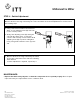
a. Remove the four (4) screws that secure the
cover plate (A) or the existing switch.
b. Mount the new switch on top of the control (B)
using the (4) screws.
The No. 2 switch can be positioned with the conduit
opening facing toward or away from the float chamber.
These are the only positions in which the switch will
function properly. See drawing at right.
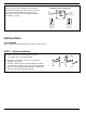
SCHEMATIC OF SWITCH OPERATION
Water Level
Normal
Burner On
Alarm Off
Low
Water
Alarm
Terminals
Low Water
Cut-Off
Terminals
C.
N.O.
N.C.
Water Level
Low
Burner Off
Alarm On
C.
N.O.
N.C.
N.
O.
N.C.
C.
The No. 2 Switch will help to maintain a minimum
water level in the boiler during normal operation.
The switch will shut off the burner in the event the
boiler water level falls. Once the water level is
restored to its normal level, the switch will allow
the burner to operate.
INSTALLATION –
TOOLS NEEDED:
One (1) flathead screwdriver and one (1) 5/16” socket wrench.
STEP 1 - Switch Installation