
Install Instructions


3
Neutral
120 V.A.C.
Supply Hot
Used as a Mainline Switch
and/or Low Water Alarm
FIGURE 1
Used as a Pilot Switch to Coil
of Relay or Motor Starter
Low
Water
Alarm
Load
Load
Line
C.
N.C.
N. O.
C.
N.C.
N. O.
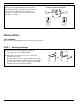
b. Using copper wire only, follow the wiring
diagrams in Figure 1 to wire the No. 2
Switch. Terminals C and NC are the low
water cut-off switch. Terminals C and NO
are the alarm switch. If the electrical load
exceeds the rating of the switch, use an
auxiliary relay or motor starter.
E
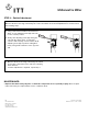
c. Slide the switch housing (E) onto the
switch and, using a flathead screwdriver,
tighten the two (2) screws that secure the
switch housing.
a. Check to see that the burner turns on and
off, by raising and lowering the water level
in the boiler.
b. Make sure there is travel in the float arm
after the burner goes on and off.
c. Repeat test several times.
E
a. Using the flathead screwdriver, remove the
two (2) screws that secure the switch housing (E).
STEP 2 - Electrical Wiring
STEP 3 - Testing
INSTALLATION COMPLETE