Service Guide Book
Table of Contents Model Name Product Name Description Nomenclature 2 3 Conversion Table Conversion Table 6 Product Mainboard vs. Handset Matrix Product Mainboard vs.
Multi Split AC Inverter Condensing Unit Multi Split DC Inverter Condensing Unit Horizontal Condensing Unit Vertical Condensing Unit Air Cooled Roof Top Packaged Air Conditioner Air Cooled Inverter Mini Chiller 17 18 19 20 21 22 Description Wall Mounted Fan Coil Unit Wall Mounted AC Inverter Fan Coil Unit Wall Mounted DC Inverter Fan Coil Unit Ceiling Exposed Fan Coil Unit Ceiling Cassette Fan Coil Unit Ceiling Concealed Fan Coil Unit Ducted Split Blower Unit Chilled Water Fan Coil Unit Water Source Heatp
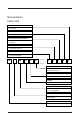
Nomenclature Indoor Unit Others A : First Issue Grille Type A : Grille A Air Treatment Devices & Control I : Negative Ion L : Bare Unit Market Region C : Export with CE mark Electrical A : 220-240V/1Ph/50Hz F : 380-415V/3Ph/50Hz M WM 010 G R - A C I A A Model Type R : Heat Pump Omitted if Cooling Only Series G : G Series Capacity 010 : 10,000 Btu/h Model Name WM : Wall Mounted CK : Ceiling Cassette Refrigerant 5 : R410A Omitted if R22 Brand M : McQuay 3
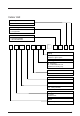
Indoor Unit Product Specifications Variation AA : Revision Connection Type F : Flare X : Not Applicable Electrical A : 220-240V/1Ph/50Hz F : 380-415V/3Ph/50Hz M WM 010 G W - A X A A Piping H : 4 Pipes System Omitted if 2 pipes system Model Type R : Heat Pump W : Chilled Water Fan Coil Omitted if DX Cooling Only Series G : G Series Capacity 010 : 10,000 Btu/h Model Name WM : Wall Mounted CK : Ceiling Cassette Refrigerant 5 : R410A Omitted if R22 Brand M : McQuay 4
Indoor Unit Others A : First Issue Specifications Variation O : Standard Unit I : Gold Fins G : Low Ambient Unit H : High Ambient Unit Compressor P : Panasonic M : Mitsubishi Market Region C : Export with CE mark Electrical A : 220-240V/1Ph/50Hz F : 380-415V/3Ph/50Hz M LC 010 C R - A C P O A Model Type R : Heat Pump Omitted if Cooling Only Series C : C Series Capacity 010 : 10,000 Btu/h Model Name LC : Single Split Condensing Unit MC : Modular Split Condensing Unit Refrigerant 5 : R410A Omitted
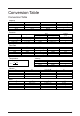
Conversion Table Conversion Table Capacity Btu/hr 1 1000 3.968 3412 MBH 0.001 1 0.004 3.412 kCal/Hr 0.252 252 1 860.04 kW -3 0.293 x 10 0.293 -3 1.162 x 10 1 Pressure kg/cm 1 14.22 -2 3.61 x 10 -4 1.45 x 10 0.07 1 -3 2.538 x 10 -4 0.1 x 10 Flow Rate W.G. 3 L/s 1 0.278 1000 0.063 0.472 m /hr 3.6 1 3600 0.227 1.7 (ft.) 2.309 32.84 0.083 -4 3.349 x 10 Pascal (Pa) 4 0.69 x 10 4 9.81 x 10 248.84 1 3 U.S. GPM 15.85 4.403 15850 1 7.481 CFM 2.119 0.588 2119 0.1337 1 m/s 0.305 1 0.005 fpm 60 196.
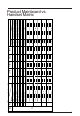
DX Type 12 11 10 1 2 3 4 5 6 7 8 9 No. Main Board (IC) Model WM - F Series WM - G Series WMS - G Series CK - A/B/C Series CE - D Series CE - E Series CC - C Series CC - D Series SB - B/C Series SB 75 – 100B/BR SB 125 – 150B/BR SB 125CR SB 150B2/BR2 – 600B4/BR4 SB – D/ER Series SB 75 – 100D/ER SB 125 – 150D/ER SB 125D2 – 500D4 SB 125ER2 – 600ER4 RT Series RT 55 – 120A/AR RT 150 – 420A/AR WMX – G Series CKX – A/C Series CEX – E Series CCX – C Series X X X L2.
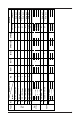
8 WSHP Mini Chiller CW FCU Type 5WMWS – GR 5CKWS – AR/CR 20 21 5CCWS – CR WH – B Series WH 11 – 20B/BR WH 25 – 70B/BR CC – CW Series SB – BW Series AC – C Series AC 20 – 60C/CR AC 80 – 150C/CR 5AC 20 – 25C/CR 5AC 30 – 55C/CR 17 18 19 22 23 CE – EW Series 16 X X X X CE – DW Series 15 CK – AW/AWH/CW Series 14 W2 X Main Board (IC) WM – GW Series Model 13 No. X X MCH1 X X MC1.0 X X X LWS2.0 X APM01CB X APM02D SLM15A APW04A SLM3 G7 G7 C. Panel C. Panel C. Panel C.
Challenger 2.2 Challenger 2.4 Challenger 2.4 Challenger 5 1996 1997 1998 1998 2002 2002 U1.4 Inverter VA1.9 (Indoor) VB1.0 (Outdoor) Sequencer Controller D2.0 Mini Chiller SZMC01 2001 D2.0 2001 G7 G7 G7 Turbo - G6 / G7 - SLM3 / Netware 2 (optional) SQ-LCD - - - - SLM3 (4 core wire) G6 G6 G6 U1.
10 Sequential Controller, SQ U1.4 L2.0 MC01 MCH01 L208A 2003 2004 2004 2004 2005 MC01 L208A Sequential Controller, SQ Chilled Water W2 2005 2006 2006 2006 2005 U1.4 Universal U1SB125 Sequential Controller, SQ Inverter VA2.0 Universal U1SB125 2003 2005 G11 - Multi Split Indoor, MS10.
Handset Operating Guide G6 Outlook 8 2 TEMP 7 6 5 4 3 FAN MODE TIMER SLEEP 1 SWING Operation Guide 1. “ON/OFF” Switch v Press to start the air conditioner unit. v Press again to stop the unit. 2. Temperature Setting v Set the desire room temperature. v Press button to increase or decrease the set temperature. Setting range are between 16°C TO 30°C setting (60°F to 80°F) (Optional setting from 20°C to 30°C). Press or button simultaneously will toggle the temperature setting between °C and °F. 3.
5. Timer Setting v Press set button to activate the timer setting (from 1 hour to 15 hour) of the air conditioning unit. It will be in “On” or “Off” condition after the set time depending to the current condition (either from “On” to Off” or vise versa) v To cancel the timer setting, press the button continuously until the timer display goes off. 6. Operation Modes v Press the “mode” button for select the type of operating mode. v Cooling only unit: Cool m Dry m Fan.
G7 Outlook 1 2 MIN HR F C AUTO AM PM ON OFF 4 3 6 12 MODE ON TIM ER 7 SET SWING F TI OF CLR SET CLOCK MER CLR EP SLE 5 8 10 9 11 Operation Guide 1. Transmission Source v The source where the signal will be transmitted. 2. Signal Transmission Indication v Blink to confirm the last setting has been send to the unit. 3. On/Off Button v Press once to start the air conditioner. v Press again to stop the unit. 4.
5. Operation Mode v Press the MODE button to select the type of operating mode. v For cooling only unit, the available modes are : COOL, DRY & FAN. v For heat pump unit, the available modes are : AUTO, COOL, DRY, FAN & HEAT. 6. Fan Speed Selection v Press the button until the desired fan speed is achieved. 7. On Timer Setting v Press the SET button will activate the on timer function. v Set the desired on time by pressing the SET button continuously. If the timer is set to 7.
G11 Outlook 2 1 4 8 10 3 5 6 7 12 11 9 Operation Guide 1. “ON/OFF” Button v Press once to start the air conditioner unit. v Press again to stop the unit. 2. Temperature Setting v To set the desired room temperature, press the ▲ button to increase or ▼ button to decrease the set temperature. v The temperature setting range is from 16°C to 30°C. v Press both buttons simultaneously to toggle ▲ and ▼ from °C to °F setting. 3. Operation Mode v Press the MODE button to select the type of operating mode.
4. Fan speed selection v Press the D button continuously will toggle the fan speed in the following order: Low ( v Med ( ) –––: High ( ) –––: Auto Stop pressing when the desired fan speed appears on the display screen. ) –––: 5. ON Timer Setting v Press the SET button will activate the on timer function. v Set the desired on time by pressing the SET button continuously. If the timer is set to 7.30am, the air conditioner will turn on at 7.30am sharp.
G17 Outlook 1 2 P1 P2 10 9 3 MODE 4 SET OFF TIMER SET ON TIMER 14 13 8 SLEEP 7 CANCEL 15 CANCEL 11 5 12 6a 6b Operation Guide 1. Transmission Source v The source where the signal will be transmitted. 2. Signal Transmission Indication v Blink to confirm that the last setting has been transmitted to the unit. 3. Temperature Setting v To set the desired room temperature, press the ▲ or ▼ button to increase or decrease the set temperature.
5. Automatic Air Swing (optional) v Press the SWING button to activate the automatic air swing function. v To distribute the air to a specific direction, press the SWING button and wait until the louver move to the desired direction and press the button once again. 6a. Silent Function v Press for quiet operation. v Fan speed turn to minimum speed. v Press again to deactivate the function. 6b.
SLM3 Outlook SLM AC-5300 (OPTIONAL) Operation Guide 1. “ON/OFF” Switch v Press to start the air conditioner unit. v Press again to stop the unit. 2. Temperature Setting v Set the desired room temperature. v Press button to increase or decrease the set temperature. Setting range are between 16 oC to 30 oC (60 oF to 80 oF). 3. Operation Modes v Press the “mode” button for select the type of operating mode.
6. “SLEEP” Mode v Press button to activate the sleep function. This function can only be activated under “cool” or heating mode operation. When it is activated under “cool” mode operation, the set temperature will increase 0.5°C after 30 minutes, 1°C after 1 hour and 2°C after 2 hours. If it is activated under “HEAT” mode operation, the set temperature will be decreased 0.5°C after 30 minutes, 1°C after 1 hour and 2°C after 2 hours. 7. Air Swing v Press button to activate the automatic air swing function.
Sequential Controller Outlook A : B : C : D : E : F : G : H : I : Time display Error indication Compressor running display (up to 4 compressors) Key lock display Heat display (up to 2 heaters) Energy saving mode display Compressor defrost cycle display (up to 4 compressors) Operation mode display Temperature set display Operating Guide 1. “ON/OFF” Switch • Press once to start the air conditioning unit. • Press again to stop the unit.
4. Auxiliary Electric Heater • If the “HEAT” mode provides insufficient heating to a room even at the highest temperature setting (30°C), press the HEATER key to activate the auxiliary electric heater. For models with two heaters, consecutive press of the key allows the selection of one or both heaters active. 5. Temperature Setting • To set the desired room temperature, press ▲ or ▲ to increase or decrease the set temperature in the range of 16°C to 30°C.
Netware 3 Outlook 4 5 6 3 7 2 1 8 1. 2. 3. 4. 5. 6. 7. 8. Time display Key lock display Error indication Fan speed display Operation mode display Sleep mode display Air swing display Temperature set display Operating Guide 1. “ON/OFF” Switch • Press once to start the air conditioning unit. • Press again to stop the unit. • The operation lamp next to the key lights up and goes off respectively when the unit is running or not running.
4. Sleep Mode Setting • Press the SLEEP key to activate sleep mode. This function is available under COOL, HEAT & AUTO mode. • When it is activated in COOL mode, the set temperature will be increased 0.5°C after 30mins, 1°C after 1 hour and 2°C after 2 hours. • When it is activated in HEAT mode, the set temperature will be decreased 1°C after 30mins, 2°C after 1 hour and 3°C after 2 hours. 5.
Controller Configuration Auto Random Restart • Shorted at JH/JP1/J_LST jumper at main board for auto restart (supplied). • Remove the jumper to have non-auto restart. D2.0 U1.5 / SQ2.0 L2.
Hot Keep Selection Three selections available: a. Fan stop if indoor coil temperature < 30°C (OFF). b. Fan runs at low speed if indoor coil temperature < 30°C and stop if indoor coil temperature < 18°C (ON). c. Cycle of low fan running for 30s and fan off for 120s and repeat (INTERVAL). WM – F/FR (U1.5) 3 selections available at the slide switch on the On/Off Switch Board; Preset at OFF. Other models (U1.5) At CN3 location on the PCB, i. Remove the connector to have (b) Fan ON and ii.
Auxiliary Heater Conversion To convert the standard U1.5 heatpump PCB to with auxiliary heater application, the following components need to be added onto the PCB. 1. Heater relay 2. Transistor 3.
Multi Split Conversion Cooling Only Model (L2.0 / L208A) The cooling only model WM-G, CK-A/B/C, CE-E, CC-C which are using L2 control board can be switched to multi split units without any modification needed. Heatpump Model (L2.0 / L208A) WM-GR The Multi Split mode can be selected at the slide switch on the On/Off Switch Board; Preset at OFF. The outdoor coil sensor has to be removed from the PCB as the reading is taken from the outdoor PCB directly.
Sequential Controller It is allowed to configure the controller to suit individual’s need with details below: Model Selection 1. Number of Compressor The control can be configured into 4 main type’s base on number of compressors by changing “R42” values: Item 1 2 3 4 Type Single compressor 2 compressors 3 compressors 4 compressors R value 3k 7.5k 22k OPEN 2. Models For each type, there are 3 models for the control to configure into. a. Cooling (SQCn) b. Heatpump + no heater (SQHn0) c.
The default differential temperature is base on number of compressor model, the setting is as below: Model 1 compressor 2 compressors 3 compressors 4 compressors Diff. Temperature Not. Applicable 0.5°C 1.0°C 1.5°C 4. Hot Keep Option Dip switch 6 Off On a. Fan off b. Fan on 5.
7. Sequential Control for Cool Mode The starting sequence for indoor fan, outdoor fan and compressors is shown as below: Start 2 seconds 15 seconds 15 seconds 15 seconds 15 seconds Indoor fan Outdoor fan 1 Outdoor fan 2 Outdoor fan 3 Outdoor fan 4 2 seconds 2 seconds 2 seconds 2 seconds Compressor 1* Compressor 2* Compressor 3* Compressor 4* *If available and applicable The compressors will be turned on one by one depending on the on/off conditions shown in the above. 8.
9. Conversion from Old Sequential Board to New Sequential Board (For wiring up to 1000 meters) 9.1 Sequential Main Board SQMB01 (Old Version) U8 Rework instruction: SQMB01 (Main Board) from old version to new version Step 1:Remove Jumper J1 and J2. Step 2:Add Part: 2051-MAX1483 IC :MAX1483 to U8 J1 & J2 9.
9.3 Sequential Main Board SQMB01 (New Version) Part: 2051-MAX1483 IC :MAX1483 Jumper J1 and J2 removed 9.4 Sequential LCD Panel SQ-LCD (New Version) SQLCD (LCD Panel) from old to new Step 1: Remove Jumper: J1, J2 Step 2: Add Chip Resistor.
Chilled Water Fan Coil Unit (W1V3) The standard W1V3 board comes with a VALVE jumper. The system can be configured as the jumper selection listed below: VALVE jumper Heatpump Mode & Valve Application Heatpump Mode & Valveless Application Cooling Mode & Valve Application Cooling Mode & Valveless Application √ : Jumper Remained HEAT jumper X X X X X : Jumper Removed VALVE & HEAT Jumper Location Model: WM 05-25FW 1. VALVE jumper is plugged into JVLV connector on the emergency switchboard. 2.
Chilled Water Fan Coil Unit (W2.0) The system model can be configured via the following jumpers. For each model selected, the permissible operating modes are as follows: Jumper M1 M2 M3 M4 Configuration 2 Pipes without Aux. Heater 2 Pipes with Aux. Heater 4 Pipes + Boiler 4 Pipes + Boiler Model 1 2 3 4 Operating Modes Heat>Cool>Dry>Fan Heat>Cool>Dry>Fan Heat>Cool>Dry>Auto>Fan Heat>Cool>Dry>Fan M1 M2 M3 M4 The standard W2.0 board comes with a VALVE jumper.
Service Diagnosis Self Diagnosis Table Wall Mounted F Series Cooling Only Model Model Board Handset WM 10/15/20/25F, 311 D2.
Wall Mounted F Series Heat Pump Model Model Board Handset WM 10/15/20/25FR, 301R U1.
Wall Mounted G Series Model Model Board Handset WM 10/15/20/25G/GR L2.
Ceiling Cassette A / B / C Series Model Model CK 20/25/30/40/50A/AR CK 15/20/25B/BR CK 10/15/20C/CR Board U1.5 U1.5 U1.
Ceiling Cassette A / B / C Series Model Model CK 20/25/30/40/50A/AR CK 15/20/25B/BR CK 10/15/20C/CR Board L208A L208A L208A Handset G7 / SLM3 / Netware 3 G7 / SLM3 / Netware 3 G7 / SLM3 / Netware 3 LED Indicator Light Display - Cooling POWER TIMER SLEEP LED Indicator Light Display – Heating POWER TIMER HEAT LED Light Diagnostic Table Operation / Faulty Indication Cooling mode Timer On Sleep mode On Heating mode Auto mode in cooling operation Auto mode in heating operation Compressor overload prot
Ceiling Exposed D Series Model Model CE 20/25/30/40/50D/DR Board U1.
Ceiling Exposed D / E Series Model Model CE 20/25/30/40/50D/DR CE 15/20/25/28E/ER Board L208A L208A Handset G7 / SLM3 / Netware 3 G11 / SLM3 / Netware 3 LED Indicator Light Display - Cooling COOL DRY FAN LED Indicator Light Display – Heating COOL DRY FAN HEAT LED Light Diagnostic Table Operation / Faulty Indication Cooling mode Dry mode Fan mode Heating mode Auto mode in cooling operation Auto mode in heating operation Compressor overload protection / Indoor coil sensor short / Outdoor coil sens
Seven Segment Display – SLM3 / Netware 3 Model WM 10/15/20/25FR, 301R CK 20 - 50A/AR CK 15 - 25B/BR CK 10 - 20C/CR CE 20 - 50D/DR CC 10 - 60C/CR Board U1.5 U1.5 U1.5 U1.5 U1.5 U1.
Ducted Blower B/C/D/ER Series Model – Single Compressor Rooftop Packaged Air Conditioner – Single Compressor Model SB 75 – 100B/BR SB 75 – 100D SB 75 – 100ER SB 125 – 150B/BR SB 125CR SB 125 – 150D SB 125 – 150ER Board L208A L208A L208A U1SB125 U1SB125 U1SB125 U1SB125 Handset SLM3 SLM3 SLM3 SLM3 SLM3 SLM3 SLM3 RT 55 – 120A/AR U1SB125 SLM3 Seven Segment Display – SLM3 Seven Segments Faulty Indication E1 blinking Room air sensor contact loose / short E2 blinking Indoor coil sensor contact open E3
Ducted Blower B/D/ER Series Model – Multi Compressors Rooftop Packaged Air Conditioner – Multi Compressors Model SB 150B2/BR2 – 600B4/BR4 SB 125D2 – 500D4 SB 125ER2 – 600ER4 Board SQ2.0 SQ2.0 SQ2.0 Handset SQ-LCD SQ-LCD SQ-LCD RT 150 – 420A/AR SQ2.0 SQ-LCD Error Code When the system is on and an error occurs, the ON/OFF LED on the LCD panel will blink and an error code is shown. When the system is off and there is a thermistor error, the ON/OFF LED is off but the error code is still displayed.
Wall Mounted F Series Inverter Model Model WMX 10/15FR Board VA2.
Wall Mounted G Series Inverter Model Model WMX 10/15/20/25G/GR Board VA3.
Ceiling Cassette A/C Series Inverter Model Model CKX 20/25A/AR CKX 10/15/20C/CR Board VA3.0 VA3.
Ceiling Convertible E Series Inverter Model Model CEX 15/20/25E/ER Board VA3.
Seven Segment Display Model WMX 10 – 25G/GR CKX 20 – 25A/AR CKX 10 – 20C/CR CEX 15 – 25E/ER CCX 10 – 25C/CR Board VA3.0 VA3.0 VA3.0 VA3.0 VA3.
Inverter Outdoor Unit Model SLX 10/15/20/25C/CR MSV 25/35A MSX 20/25/30A/AR Normal running / compressor running RED LED blinking No.
Chilled Water Fan Coil Unit Model WM 05 – 25FW, 301W CK 20 – 50AW/AWH CK 15 – 25BW CK 10 – 20CW CE 20 – 50DW/CBW CC 10 – 60CW SB 75 – 150BW Board W1V3 W1V3 W1V3 W1V3 W1V3 W1V3 N/A Handset G7 / SLM3 / Netware 3 G7 / SLM3 / Netware 3 G7 / SLM3 / Netware 3 G7 / SLM3 / Netware 3 G7 / SLM3 / Netware 3 SLM3 / Netware 3 No Controller Self Diagnostic Table – W1V3 Fault Indication POWER LED / COOL LED Other LEDs Seven Segments Room sensor missing Blinks 4 times FAN blinks E1 blinking Indoor coil sensor missing Bl
Wall Mounted G Series Model – Water Source Split Unit Model 5WMWS 10/15/20/25GR Board LWS2.
Ceiling Cassette A / B / C Series Model – Water Source Split Unit Model 5CKWS 20/25/30/40/50AR 5CKWS 10/15/20CR Board LWS2.0 LWS2.
Seven Segment Display – SLM3 / Netware 3 (Water Source Split Unit) Model 5WMWS 10/15/20/25GR 5CKWS 20 - 50A/AR 5CKWS 10 - 20C/CR 5CCWS 10 - 60C/CR Board LWS2.0 LWS2.0 LWS2.0 LWS2.
General Check When any air conditioner malfunction is noted, immediately switch off the power supply to the unit and contact the local dealer if necessary.
General Troubleshooting Guide By means of pressure readings. Low Side High Side Low Side High Side Low Side High Side Low Side High Side Too High Normal Probable Cause A Little High Circuit High Side Too Low Data A Little Low Pressure 1. Overcharged with refrigerant. 2. Non-condensable gases in refrigerant circuit (eg. Oil) 3. Obstructed air-intake / discharge. 4. Short circuit of hot air at condensing unit. 1. Poor compression / no compression (compressor defective). 2.
By means of diagnostic flow chart: Generally, there are two kinds of problems, i.e. starting failure and insufficient cooling/heating. “Starting failure” is caused by electrical defect while improper application or defects in refrigerant circuit causes “Insufficient cooling / heating”.
1 2 Faulty Condenser fan contactor Coil burnt Change the contactor Contact faulty Change the contacts Fan motor faulty Other electrical component faulty Faulty Compressor contactor Repair or change the motor contactor Repair or change if necessary Coil burnt Change the contactor Contact faulty Change the contacts Open compressor windings Incorrect wiring Change the compressor Correct the wiring The most common causes of air conditioner failure to “start” are : a) Voltage not within p 10% of
ii ) Diagnosis of Refrigerant Circuit / Application There might be some causes where the unit starts running but does not perform satisfactorily, i.e. insufficient cooling. Judgement could be made by measuring temperature difference of indoor unit’s intake and discharge air as well as running current.
Insufficient heating Restricted Air circulation Indoor / outdoor coil dirty (clogged) Indoor air filter dirty Fan motor malfunction Obstruction at air inlet / outlet of indoor / outdoor unit High heating load Refrigerant circuit Windows / doors wide open Refrigerant short charge or refrigerant leakage Restriction e.g. at strainer, capillary, filter dryer, etc.
62 v v v Remedial Action v Check power supply v Look for short circuit or grounded wires in motor windings Replace fuses and reset circuit breakers when the fault has been corrected Check tightness and soundness of all electrical connection Defective contactor or coil v Repair or replace Unit is stopped because a safety has tripped v Determine the type of safety shut down and correct the unit is restarted Loose wires v Check wire connection and tighten terminal screw Compressor faulty v Contact local dea
63 Switch (ON) Cool air does not come out Compressor run but stops immediately Water or steam is discharged from the unit Fan runs but compressor does not run Switch (ON) Air flow out but it does not cool enough Troubleshooting v Close the windows and doors v Wait for a while (to protect the compressor, a 3 minutes restart-preventing circuit is built into the unit. Therefore, there are occasions sometimes when the compressor does not start running immediately.
Appendix Resistance – Temperature Characteristics Type Material Name Resistance B Value DTN-C1 03F3H-OYL 1128, 1148, 1158 3H R25=10.000k + 1.0% - 1.0% B25/30=3450K + 1.0% - 1.0% t°C Rmin (k ) Rnom (k ) Rmax (k ) t°C Rmin (k ) Rnom (k ) Rmax (k ) 42 5.28E+00 5.37E+00 5.45E+00 44 4.92E+00 5.01E+00 5.09E+00 3.49E+01 46 4.59E+00 4.67E+00 4.76E+00 3.04E+01 3.11E+01 3.18E+01 48 4.29E+00 4.37E+00 4.42E+00 0 2.78E+01 2.84E+01 2.90E+01 50 4.01E+00 4.09E+00 4.16E+00 2 2.54E+01 2.
Lot 60334, Persiaran Bukit Rahman Putra3, Taman Perindustrian Bukit Rahman Putra, P.O.Box 79, 47000 Sungai Buloh, Selangor D.E., Malaysia Tel: 603-61458600 Fax: 60361412060 http://www.mcquayup.