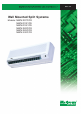
MWM - 2005 Wall Mounted Split Systems Models: MWM 007F/FR MWM 010F/FR MWM 015F/FR MWM 020F/FR MWM 025F/FR MWM 030F/FR
Contents Features ...................................................................................................................... 1 Nomenclature ............................................................................................................. 2 Specifications ............................................................................................................ 3 Performance Table ...................................................................................................
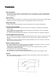
Fea tur es eatur tures • Easy Installation - The wall mounted fan coil unit is easily installed because of its compact size, slimness and light weight. - Slim and short outdoor unit can be easily installed even in a narrow balcony and passageway and yet have a stable profile. • Space Saving - No space is required on either floor or ceiling. This newly developed super slim design for wall mounting maximizes floor space usage and enhances ceiling appearance where ceilings are low.
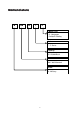
Nomenc la tur e Nomencla latur ture M WM 025 F R Model Type R : Heatpump Omitted if Cooling Series F : F Series Capacity 25 : 25,000 Btu/h Model Name WM : Wall Mounted Brand M : McQuay 2
Specif ica tions Specifica ications R22 Models (Cooling Only) INDOOR UNIT OUTDOOR UNIT MODEL NOMINAL COOLING CAPACITY W Btu/h V / Ph / Hz L/s / cfm COIL FIN mm / in mm / in mm / in m2 / ft2 mm / in mm / in mm / in kg / lb dBA mm / in mm / in mm / in mm / in V / Ph / Hz TUBE FIN COIL PIPE OUTDOOR UNIT FAN COMP.
R22 Models (Cooling Only) NOMINAL COOLING CAPACITY COIL FIN FIN PIPE COIL TUBE FAN COMPRESSOR INDOOR UNIT TUBE FAN INPUT POWER RUNNING CURRENT POWER SOURCE REFRIGERANT / CONTROL FAN TYPE AIR FLOW FAN MOTOR RATED INPUT POWER RATED RUNNING CURRENT FAN MOTOR PROTECTION MATERIAL TUBE PATTERN DIAMETER THICKNESS MATERIAL THICKNESS ROW FIN PER INCH FACE AREA HEIGHT DIMENSION WIDTH DEPTH WEIGHT SOUND PRESSURE LEVEL - H/M/L ROOM TEMPERATURE CONTROL AIR DISCHARGE OPERATION CONDENSATE DRAIN SIZE AIR FILTER
R22 Models (Heatpump) INDOOR UNIT OUTDOOR UNIT MODEL W Btu/h W Btu/h NOMINAL COOLING CAPACITY NOMINAL HEATING CAPACITY COOLING HEATING COOLING HEATING INPUT POWER (W) - 1∅ [3∅] RUNNING CURRENT (A) - 1∅ [3∅] V / Ph / Hz L/s / cfm COIL mm / in mm / in mm / in FIN INDOOR UNIT TUBE FAN POWER SOURCE REFRIGERANT / CONTROL FAN TYPE AIR FLOW FAN MOTOR RATED INPUT POWER (W) RATED RUNNING CURRENT (A) FAN MOTOR PROTECTION MATERIAL TUBE PATTERN DIAMETER THICKNESS MATERIAL THICKNESS ROW FIN PER INCH FACE AR
R22 Models (Heatpump) INDOOR UNIT OUTDOOR UNIT MODEL NOMINAL COOLING CAPACITY NOMINAL HEATING CAPACITY W Btu/h W Btu/h W W A A V / Ph / Hz COIL FIN TUBE FIN COIL PIPE OUTDOOR UNIT FAN COMPRESSOR INDOOR UNIT TUBE FAN INPUT POWER (COOLING) - 1∅ <3∅> INPUT POWER (HEATING) - 1∅ <3∅> RUNNING CURRENT(COOLING) - 1∅ <3∅> RUNNING CURRENT (HEATING) - 1∅ <3∅> POWER SOURCE REFRIGERANT / CONTROL FAN TYPE AIR FLOW L/s / cfm FAN MOTOR RATED INPUT POWER W RATED RUNNING CURRENT A FAN MOTOR PROTECTION MATERIAL
R407C Models (Cooling Only) INDOOR UNIT OUTDOOR UNIT MODEL NOMINAL COOLING CAPACITY COIL FIN TUBE FIN COIL PIPE OUTDOOR UNIT FAN COMPRESSOR INDOOR UNIT TUBE FAN INPUT POWER 1∅ < 3∅ > RUNNING CURRENT 1∅ < 3∅ > POWER SOURCE REFRIGERANT / CONTROL AIR FLOW FAN MOTOR RATED INPUT POWER RATED RUNNING CURRENT FAN MOTOR PROTECTION MATERIAL DIAMETER THICKNESS MATERIAL THICKNESS ROW FIN PER INCH FACE AREA HEIGHT DIMENSION WIDTH DEPTH WEIGHT SOUND PRESSURE LEVEL ROOM TEMPERATURE AIR DISCHARGE CONTROL OPERA
R407C Models (Cooling Only) INDOOR UNIT OUTDOOR UNIT MODEL NOMINAL COOLING CAPACITY COIL FIN TUBE FIN COIL PIPE OUTDOOR UNIT FAN COMPRESSOR INDOOR UNIT TUBE FAN INPUT POWER - 1∅ / < 3∅ > RUNNING CURRENT - 1∅ / < 3∅ > POWER SOURCE REFRIGERANT / CONTROL FAN TYPE AIR FLOW FAN MOTOR RATED INPUT POWER RATED RUNNING CURRENT FAN MOTOR PROTECTION MATERIAL TUBE PATTERN DIAMETER THICKNESS MATERIAL THICKNESS ROW FIN PER INCH FACE AREA HEIGHT DIMENSION WIDTH DEPTH WEIGHT SOUND PRESSURE LEVEL - H/M/L ROOM
R407C Models (Heatpump) INDOOR UNIT OUTDOOR UNIT MODEL NOMINAL COOLING CAPACITY NOMINAL HEATING CAPACITY COOLING HEATING COOLING RUNNING CURRENT 1∅ < 3∅ > HEATING POWER SOURCE REFRIGERANT / CONTROL AIR FLOW FAN MOTOR RATED INPUT POWER RATED RUNNING CURRENT FAN MOTOR PROTECTION MATERIAL DIAMETER THICKNESS MATERIAL THICKNESS ROW FIN PER INCH FACE AREA HEIGHT DIMENSION WIDTH DEPTH WEIGHT SOUND PRESSURE LEVEL ( H / M / L ) ROOM TEMPERATURE CONTROL AIR DISCHARGE OPERATION CONDENSATE DRAIN SIZE AIR FILTER HEIGH
R407C Models (Heatpump) INDOOR UNIT OUTDOOR UNIT MODEL NOMINAL COOLING CAPACITY NOMINAL HEATING CAPACITY COIL FIN TUBE FIN COIL PIPE OUTDOOR UNIT FAN COMPRESSOR INDOOR UNIT TUBE FAN INPUT POWER (COOLING) - 1∅ / < 3∅ > INPUT POWER (HEATING) - 1∅ / < 3∅ > RUNNING CURRENT(COOLING) - 1∅ / < 3∅ > RUNNING CURRENT (HEATING) - 1∅ / < 3∅ > POWER SOURCE REFRIGERANT / CONTROL FAN TYPE AIR FLOW FAN MOTOR RATED INPUT POWER RATED RUNNING CURRENT FAN MOTOR PROTECTION MATERIAL TUBE PATTERN DIAMETER THICKNESS
Perf or mance Table erfor ormance Interpolation and Extrapolation method can be used to get the total capacity, TC and sensible capacity, SC at those temperatures which are not stated out in the table. Example: Model: MWM 010F / MLC 010C Indoor Condition: 23°C DB, 15°C WB Outdoor Condition: 37°C DB Solution: Overall Based on the Performance table on Pg.(15), 1. Refer to the Indoor DB column, - 23°C is located between 20°C and 24°C (Thus, Interpolation need to be applied) 2.
Details: st 1 Step: To obtain the Total capacity and Sensible capacity for (a) Indoor Condition: 24°C DB, 15°C WB Outdoor Condition: 35°C DB Indoor DB °C Indoor WB °C Outdoor DB, °C 35 TC (kW) SC (kW) 15 16 17 24 x1 2.582 2.659 y1 1.835 1.739 Total capacity, TC => x1 = 2.506kW (Same as Total capacity at 20°C Indoor DB / 15°C Indoor WB & 35°C Outdoor WB)* Sensible capacity, SC Extrapolation Method: 1 .739kW − y 1 17 ° C − 15° C => = ° 17°C − 16 C 1.739 kW − 1.835kW => y1 = 1.
nd 2 Step: To obtain the Total capacity and Sensible capacity for (a) Indoor Condition: 23°C DB, 15°C WB Outdoor Condition: 35°C DB Indoor DB °C Indoor WB °C 20 23 24 15 15 15 Outdoor DB, °C 35 TC (kW) SC (kW) 2.506 x3 2.506 1.363 y3 1.931 Total capacity, TC ⇒ x3 = 2.506kW (Same as Total capacity at 20°C Indoor DB / 15°C Indoor WB & 35°C Outdoor WB)* Sensible capacity, SC Interpolation Method: ⇒ 24° C − 20° C 1.931kW −1.363kW = 24°C − 23° C 1.931kW − y 3 ⇒ y3 = 1.
rd 3 Step: To obtain the Total capacity and Sensible capacity for (a) Indoor Condition: 23°C DB, 15°C WB Outdoor Condition: 37°C DB Indoor DB °C Indoor WB °C TC (kW) 23 15 2.506 35 Outdoor DB, °C 37 SC (kW) TC (kW) SC (kW) 1.789 Total capacity, TC Interpolation Method: ⇒ 40 ° C − 35 ° C 2.311kW − 2.506kW = 2.311kW − x 40°C − 37 ° C ⇒ x = 2.428kW Sensible capacity, SC Interpolation Method: ⇒ 40 ° C − 35 ° C 1.631kW − 1.789kW = 40°C − 37 ° C 1.631kW − y ⇒ y = 1.
R22 Models (Cooling Only) Model : MWM 010F / MLC 010C Outdoor DB°C ID DB°C 20 24 28 30 ID WB°C 15 16 16 17 18 19 20 18 19 20 21 22 23 24 20 21 22 23 24 20 TC(kW) 3.090 3.197 3.197 3.304 3.412 3.519 3.627 3.412 3.519 3.627 3.736 3.844 3.953 4.061 3.627 3.736 3.844 3.953 4.061 25 SC(kW) 1.839 1.675 2.243 2.079 1.915 1.751 1.586 2.483 2.319 2.154 1.989 1.824 1.658 1.493 2.439 2.273 2.108 1.943 1.777 TC(kW) 2.895 2.992 2.992 3.089 3.186 3.284 3.387 3.186 3.284 3.387 3.494 3.601 3.708 3.814 3.387 3.494 3.
R22 Models (Cooling Only) Model : MWM 020F / MLC 020B Outdoor DB°C ID DB°C ID WB°C 20 24 28 30 15 16 16 17 18 19 20 18 19 20 21 22 23 24 20 21 22 23 24 20 TC(kW) 5.371 5.587 5.587 5.802 6.018 6.234 6.448 6.018 6.234 6.448 6.661 6.875 7.088 7.301 6.448 6.661 6.875 7.088 7.301 25 SC(kW) 3.206 2.923 3.830 3.547 3.264 2.980 2.695 4.172 3.888 3.603 3.316 3.028 2.741 2.454 4.057 3.770 3.482 3.195 2.908 TC(kW) 5.139 5.351 5.351 5.562 5.774 5.985 6.183 5.774 5.985 6.183 6.373 6.563 6.753 6.943 6.183 6.373 6.
R22 Models (Cooling Only) Model : MWM 030F / MLC 030B Outdoor DB°C ID DB°C ID WB°C 20 25 30 35 40 46 TC(kW) SC(kW) TC(kW) SC(kW) TC(kW) SC(kW) TC(kW) SC(kW) TC(kW) SC(kW) TC(kW) SC(kW) 15 7.743 4.459 7.364 4.208 6.985 3.957 6.606 3.706 6.227 3.454 5.773 3.153 16 8.254 4.098 7.804 3.892 7.354 3.686 6.903 3.48 6.453 3.273 5.913 3.026 16 8.254 5.486 7.804 5.28 7.354 5.074 6.903 4.868 6.453 4.662 5.913 4.415 17 8.765 5.125 8.244 4.964 7.722 4.803 7.2 4.
R22 Models (Heatpump) Model : MWM 010FR / MLC 010CR Cooling Mode Outdoor DB°C ID DB°C ID WB°C 20 24 28 30 20 TC(kW) 3.165 3.260 3.260 3.355 3.450 3.546 3.642 3.450 3.546 3.642 3.738 3.835 3.932 4.029 3.642 3.738 3.835 3.932 4.029 15 16 16 17 18 19 20 18 19 20 21 22 23 24 20 21 22 23 24 25 SC(kW) 1.854 1.681 2.288 2.114 1.941 1.768 1.594 2.548 2.375 2.201 2.026 1.851 1.675 1.500 2.504 2.329 2.154 1.979 1.804 TC(kW) 2.945 3.030 3.030 3.114 3.199 3.283 3.377 3.199 3.283 3.377 3.477 3.577 3.677 3.777 3.
R22 Models (Heatpump) Model : MWM 015FR / MLC 015CR Cooling Mode Outdoor DB°C ID DB°C ID WB°C 20 24 28 30 20 TC(kW) 3.521 3.747 3.747 3.973 4.199 4.426 4.653 4.199 4.426 4.653 4.881 5.110 5.338 5.566 4.653 4.881 5.110 5.338 5.566 15 16 16 17 18 19 20 18 19 20 21 22 23 24 20 21 22 23 24 25 SC(kW) 2.168 2.074 2.672 2.578 2.484 2.391 2.297 3.082 2.988 2.894 2.800 2.706 2.612 2.518 3.193 3.099 3.005 2.911 2.817 TC(kW) 3.335 3.528 3.528 3.721 3.913 4.106 4.310 3.913 4.106 4.310 4.522 4.733 4.945 5.156 4.
R22 Models (Heatpump) Model : MWM 020FR / MLC 020BR Cooling Mode Outdoor DB°C ID DB°C ID WB°C 20 24 28 30 15 16 16 17 18 19 20 18 19 20 21 22 23 24 20 21 22 23 24 20 TC(kW) 5.685 6.068 6.068 6.451 6.835 7.218 7.604 6.835 7.218 7.604 7.992 8.379 8.767 9.155 7.604 7.992 8.379 8.767 9.155 25 SC(kW) 3.279 3.097 4.162 3.979 3.797 3.614 3.432 4.862 4.679 4.497 4.315 4.133 3.951 3.770 5.030 4.848 4.666 4.484 4.302 TC(kW) 5.363 5.683 5.683 6.003 6.323 6.642 6.988 6.323 6.642 6.988 7.351 7.714 8.078 8.441 6.
R22 Models (Heatpump) Model : MWM 025FR / MLC 025BR Cooling Mode Outdoor DB°C ID DB°C ID WB°C 20 24 28 30 15 16 16 17 18 19 20 18 19 20 21 22 23 24 20 21 22 23 24 20 TC(kW) 6.472 7.321 7.321 8.170 9.019 9.868 10.724 9.019 9.868 10.724 11.584 12.445 13.306 14.166 10.724 11.584 12.445 13.306 14.166 25 SC(kW) 3.547 3.316 4.314 4.083 3.851 3.619 3.389 4.849 4.618 4.388 4.158 3.929 3.700 3.471 4.887 4.658 4.429 4.200 3.971 TC(kW) 6.177 6.853 6.853 7.528 8.204 8.879 9.621 8.204 8.879 9.621 10.407 11.
R22 Models (Heatpump) Model : MWM 030FR / MLC 030BR COOLING MODE Outdoor DB°C ID DB°C ID WB°C 20 25 30 35 40 46 TC(kW) SC(kW) TC(kW) SC(kW) TC(kW) SC(kW) TC(kW) SC(kW) TC(kW) SC(kW) TC(kW) SC(kW) 20 24 28 30 15 8.004 4.615 7.551 4.231 7.097 3.847 6.644 3.462 6.191 3.078 5.647 2.617 16 8.235 4.197 7.778 3.872 7.322 3.547 6.866 3.223 6.41 2.898 5.862 2.508 16 8.235 5.794 7.778 5.469 7.322 5.144 6.866 4.819 6.41 4.495 5.862 4.105 17 8.465 5.375 8.006 5.
R22 Models (Heatpump) Model : MWM 030FR / MLC 030CR Cooling Mode Outdoor DB°C ID DB°C ID WB°C 20 24 28 30 15 16 16 17 18 19 20 18 19 20 21 22 23 24 20 21 22 23 24 20 TC(kW) 8.826 9.257 9.257 9.687 10.117 10.547 10.978 10.117 10.547 10.978 11.409 11.840 12.272 12.703 10.978 11.409 11.840 12.272 12.703 25 SC(kW) 4.927 4.261 5.868 5.201 4.534 3.867 3.195 6.142 5.475 4.802 4.126 3.450 2.774 2.098 5.606 4.930 4.254 3.578 2.902 TC(kW) 8.373 8.760 8.760 9.148 9.535 9.922 10.316 9.535 9.922 10.316 10.715 11.
R407C Models (Cooling Only) Model : MWM 007F / M4LC 007B Outdoor DB°C ID DB°C ID WB°C 20 24 28 30 15 16 16 17 18 19 20 18 19 20 21 22 23 24 20 21 22 23 24 20 TC(kW) 2.602 2.633 2.633 2.664 2.694 2.725 2.756 2.694 2.725 2.756 2.788 2.819 2.851 2.883 2.756 2.788 2.819 2.851 2.883 25 SC(kW) 1.456 1.332 1.914 1.790 1.665 1.541 1.415 2.247 2.123 1.997 1.871 1.744 1.617 1.491 2.288 2.162 2.035 1.909 1.782 TC(kW) 2.406 2.438 2.438 2.471 2.503 2.535 2.572 2.503 2.535 2.572 2.613 2.654 2.695 2.736 2.572 2.
R407C Models (Cooling Only) Model : MWM 015F / M4LC 015B Outdoor DB°C ID DB°C ID WB°C 20 24 28 30 15 16 16 17 18 19 20 18 19 20 21 22 23 24 20 21 22 23 24 20 TC(kW) 3.138 3.370 3.370 3.602 3.834 4.066 4.299 3.834 4.066 4.299 4.533 4.767 5.001 5.235 4.299 4.533 4.767 5.001 5.235 25 SC(kW) 1.749 1.645 2.253 2.148 2.044 1.940 1.835 2.652 2.548 2.443 2.338 2.234 2.129 2.024 2.747 2.642 2.538 2.433 2.328 TC(kW) 2.984 3.180 3.180 3.376 3.573 3.769 3.976 3.573 3.769 3.976 4.190 4.405 4.619 4.834 3.976 4.
R407C Models (Cooling Only) Model : MWM 025F / M4LC 025B Outdoor DB°C ID DB°C ID WB°C 20 24 28 30 15 16 16 17 18 19 20 18 19 20 21 22 23 24 20 21 22 23 24 20 TC(kW) 5.842 6.317 6.317 6.792 7.266 7.741 8.218 7.266 7.741 8.218 8.697 9.176 9.654 10.133 8.218 8.697 9.176 9.654 10.133 25 SC(kW) 3.251 3.027 4.115 3.891 3.667 3.443 3.219 4.755 4.531 4.307 4.083 3.859 3.635 3.412 4.851 4.627 4.403 4.179 3.956 TC(kW) 5.577 5.978 5.978 6.378 6.779 7.179 7.600 6.779 7.179 7.600 8.035 8.470 8.905 9.340 7.600 8.
R407C Models (Heatpump) Model : MWM 007FR / M4LC 007BR Cooling Mode Outdoor DB°C ID DB°C ID WB°C 20 24 28 30 20 TC(kW) 2.685 2.673 2.673 2.660 2.647 2.635 2.622 2.647 2.635 2.622 2.609 2.596 2.584 2.571 2.622 2.609 2.596 2.584 2.571 15 16 16 17 18 19 20 18 19 20 21 22 23 24 20 21 22 23 24 25 SC(kW) 1.492 1.327 1.939 1.773 1.608 1.442 1.275 2.220 2.055 1.888 1.720 1.551 1.383 1.215 2.194 2.026 1.858 1.689 1.521 TC(kW) 2.486 2.489 2.489 2.491 2.493 2.495 2.496 2.493 2.495 2.496 2.495 2.495 2.495 2.
R407C Models (Heatpump) Model : MWM 010FR / M4LC 010BR Cooling Mode Outdoor DB°C ID DB°C ID WB°C 20 24 28 30 20 TC(kW) 2.848 2.968 2.968 3.088 3.208 3.328 3.449 3.208 3.328 3.449 3.570 3.692 3.813 3.934 3.449 3.570 3.692 3.813 3.934 15 16 16 17 18 19 20 18 19 20 21 22 23 24 20 21 22 23 24 25 SC(kW) 1.622 1.494 2.064 1.936 1.809 1.681 1.553 2.378 2.251 2.122 1.994 1.866 1.737 1.609 2.407 2.279 2.150 2.022 1.894 TC(kW) 2.669 2.774 2.774 2.879 2.983 3.088 3.201 2.983 3.088 3.201 3.319 3.437 3.555 3.
R407C Models (Heatpump) Model : MWM 015FR / M4LC 015BR Cooling Mode Outdoor DB°C ID DB°C ID WB°C 20 24 28 30 20 TC(kW) 3.144 3.280 3.280 3.416 3.552 3.688 3.823 3.552 3.688 3.823 3.958 4.093 4.228 4.364 3.823 3.958 4.093 4.228 4.364 15 16 16 17 18 19 20 18 19 20 21 22 23 24 20 21 22 23 24 25 SC(kW) 1.817 1.656 2.253 2.092 1.931 1.770 1.608 2.529 2.368 2.205 2.042 1.878 1.715 1.551 2.504 2.341 2.177 2.013 1.850 TC(kW) 3.001 3.130 3.130 3.259 3.389 3.518 3.643 3.389 3.518 3.643 3.764 3.886 4.008 4.
R407C Models (Heatpump) Model : MWM 020FR / M4LC 020BR Cooling Mode Outdoor DB°C ID DB°C ID WB°C 20 24 28 30 20 TC(kW) 5.236 5.589 5.589 5.942 6.295 6.648 7.003 6.295 6.648 7.003 7.361 7.718 8.075 8.432 7.003 7.361 7.718 8.075 8.432 15 16 16 17 18 19 20 18 19 20 21 22 23 24 20 21 22 23 24 25 SC(kW) 2.879 2.711 3.776 3.608 3.440 3.272 3.105 4.505 4.337 4.170 4.002 3.834 3.667 3.499 4.702 4.534 4.367 4.199 4.032 TC(kW) 4.940 5.234 5.234 5.529 5.823 6.118 6.436 5.823 6.118 6.436 6.771 7.105 7.440 7.
R407C Models (Heatpump) Model : MWM 025FR / M4LC 025BR Cooling Mode Outdoor DB°C ID DB°C ID WB°C 20 24 28 30 20 TC(kW) 5.528 6.253 6.253 6.979 7.704 8.429 9.160 7.704 8.429 9.160 9.895 10.630 11.365 12.100 9.160 9.895 10.630 11.365 12.100 15 16 16 17 18 19 20 18 19 20 21 22 23 24 20 21 22 23 24 25 SC(kW) 2.786 2.588 3.587 3.389 3.191 2.993 2.796 4.190 3.992 3.795 3.599 3.404 3.208 3.012 4.294 4.099 3.903 3.707 3.512 TC(kW) 5.276 5.853 5.853 6.430 7.007 7.584 8.218 7.007 7.584 8.218 8.889 9.560 10.
R407C Models (Heatpump) Model : MWM 030FR / M4LC 030CR Cooling Mode Outdoor DB°C ID DB°C ID WB°C 20 24 28 30 20 TC(kW) 8.532 8.948 8.948 9.364 9.779 10.195 10.612 9.779 10.195 10.612 11.029 11.446 11.863 12.280 10.612 11.029 11.446 11.863 12.280 15 16 16 17 18 19 20 18 19 20 21 22 23 24 20 21 22 23 24 25 SC(kW) 4.673 4.029 5.636 4.992 4.347 3.702 3.052 5.954 5.310 4.660 4.006 3.353 2.699 2.046 5.463 4.810 4.156 3.503 2.849 TC(kW) 8.094 8.468 8.468 8.843 9.217 9.591 9.972 9.217 9.591 9.972 10.358 10.
Oper ating R ang e Opera Rang ange Cooling only Cooling ! Outdoor temp. (°CDB) 54 HIGH AMBIENT UNIT 46 Cautions The use of your air conditioner outside the range of working temperature and humidity can result in serious failure. 35 STD 19 LOW AMBIENT KIT -5 24 15 Indoor temp. (°CWB) Heat pump Heating Cooling 54 Outdoor temp. (°CDB) Outdoor temp. (°CWB) 18 6 STD -9 HIGH AMBIENT UNIT 46 35 STD 19 LOW AMBIENT KIT -5 15 21 27 15 Indoor temp. (°CDB) 24 Indoor temp.
Noise Le vel Lev Sound Pressure Level (Measured In Anechoic Room) Wall Mounted Fan Coil Unit Model Speed MWM 007F/FR High Medium Low High Medium Low High Medium Low High Medium Low High Medium Low High Medium Low MWM 010F/FR MWM 015F/FR MWM 020F/FR MWM 025F/FR MWM 030F MWM 030FR 1/1 Octave A-weighted Sound Pressure (dBA), ref 20µPa 125Hz 250Hz 500Hz 1kHz 2kHz 4kHz 8kHz 35 27 27 35 32 28 35 33 31 39 37 34 41 38 36 42 40 37 34 28 25 34 29 26 34 31 28 42 40 37 46 43 42 46 45 43 36 30 28 36 32 29 36
MWM 007F/FR NC Curves MWM 010F/FR NC Curves 35
MWM 015F/FR NC Curves MWM 020F/FR NC Curves 36
MWM 025F/FR NC Curves MWM 030F / 030FR NC CURVES 37
Outlines And Dimension Indoor Unit Model: MWM 010F / 010FR / 015F / 015FR Note : Dimension in mm Outdoor Unit Model: M4LC 007B/ 007BR / 010B / 010BR / 015B / 015BR Note : Dimension in mm 38
Indoor Unit MODEL : MWM 020F / 020FR / 025F / 025FR Outdoor Unit Model : MLC 020B / 020BR / 025B / 025BR / 030B / 030BR M4LC 020B / 020BR / 025R / 025BR 39
Indoor Unit Model : MWM 030F / 030FR Note : Dimension in mm Outdoor Unit Model : MLC 030C, MLC 030CR M4LC 030C, M4LC 030CR Note : Dimension in mm 40
Indoor Unit Model : MWM 010F / 010FR / 015F / 015FR Outdoor Unit Model : MLC 010C / 010CR / 015C / 015CR 41
R efrig er ant Cir cuit Refrig efriger erant Circuit Cooling Only Models Model : M4LC 007B / 010B / 015B / 020B MLC 010C / 015C Model : MLC / M4LC 025B , MLC 030B 42
Model : MLC 030B Model : MLC / M4LC 030C 43
Heatpump Models Model : M4LC 007BR / 010BR , MLC 010CR Model : M4LC 015BR 44
Model : MLC 015CR Model : MLC / M4LC 020BR 45
Model : MLC / M4LC 025BR , MLC 030BR Model : MLC / M4LC 030CR 46
W iring Dia gram Diag Cooling Only Models Indoor Unit Model : MWM 007F / 010F / 015F (D2.0 I.C.
Indoor Unit Model : MWM 020F / 025F (D2.0 I.C.
Indoor Unit Model : MWM 020F / 025F (D2.0 I.C.
Outdoor Unit Model : MLC 030B 1 PHASE 220 - 240V 50Hz Indoor Unit Model : MWM 030F (D2.0 I.C.
Indoor Unit Model : MWM 030F (D2.01.
Indoor Unit Model : MWM 030F (D2.01.C.
Indoor Unit Model : MWM 015F (D2.0 I.C.
Indoor Unit Model : MWM 010F (D2.0 I.C.
Heatpump Models Indoor Unit Model : MWM 007FR / 010FR / 015FR (U1.4 I.C.
Indoor Unit Model : MWM 020FR / 025FR (U1.4 I.C.
Indoor Unit Model : MWM 020FR / 025FR (U1.4 I.C.
Indoor Unit Model : MWM 030FR (U1.4 1.
Indoor Unit Model : MWM 030FR (U1.4 1.C.
Indoor Unit Model : MWM 030FR (U1.4 I.C.
Indoor Unit Model : MWM 010FR (U1.4 I.C.
Indoor Unit Model : MWM 015FR (U1.4 I.C.
High Ambient Unit (Optional) Cooling Only Models Outdoor Unit Model : MLC 020B / 025B 50HZ / 1 Phase / 220 – 240V Outdoor Unit Model : MLC 030C 50HZ / 1 Phase / 220 – 240V 63
Heatpump Models Outdoor Unit Model : MLC 020BR / 025BR 50HZ / 1 Phase / 220 – 240V Outdoor Unit Model : MLC 030CR 50HZ / 1 Phase / 220 – 240V 64
Low Ambient Unit (Optional) Cooling Only Models Outdoor Unit Model : MLC 010C 50Hz/ 1 Phase / 220-240V Outdoor Unit Model : MLC 015C 50Hz / 1 PHASE / 220 - 240V 65
Cooling Only Models Outdoor Unit Model : MLC 010B / 015B 50HZ / 1 Phase / 220~240V Outdoor Unit Model : MLC 020B / 025B 50HZ / 1 Phase / 220~240V 66
Heatpump Models Outdoor Unit Model : MLC 010BR / 015BR 50HZ / 1 Phase / 220 – 240V Outdoor Unit Model : MLC 020BR 50HZ / 1 Phase / 220 – 240V Outdoor Unit Model : MLC 025BR 50HZ / 1 Phase / 220 – 240V 67
Saf ety Pr ecaution Bef or e Installa tion Safety Precaution Befor ore Installation Before operating, please read the following “Safety Precautions” carefully. To prevent injury to the user or other people and properties damage, the following instructions must be followed. ! Incorrect operation due to ignoring of instruction will cause harm or damage, the seriousness is classified by the following indications. Warning: This sign indicates the possibility of causing death or serious injury.
Symbol (with white background) denotes item that is PROHIBITED from doing. Symbol (with black background) denotes item that is COMPULSORY to be carried out. ! Caution Please confirm the following important points when installation • Grounding is necessary It may cause electrical shock if grounding is not perfect. • Do not install the unit where leakage of flammable gas may occur In case of gas leaks and accumulates at the surrounding of the unit, it may cause fire ignition.
Special Pr ecautions F or R407C Precautions For Special Precautions When Dealing With Refrigerant R407C Unit 1) What is new refrigerant R407C? R407C is a zeotropic refrigerant mixture which has Zero Ozone Depletion Potential (ODP = 0) and thus conformed to the Montreal Protocol regulation. It requires Polyol-ester oil (POE) oil for its compressor’s lubricant. Its refrigerant capacity and performance are about the same as the refrigerant R22.
b) Ensure that the compressor is not expose to open air for more than the recommended time specified by its manufacturer (typically less than 10 minutes). Removed the seal-plugs only when the compressor is about to be brazed. c) The system should be thoroughly vacuumed to 1.0 Pa (-700mmHg) or lower. This vacuuming level is more stringent than R22 system so as to ensure no incompressible gas and moisture in the system.
Installa tion Installation Installation Diagram 72
CAUTION: Before installing the unit, ensure that the power supply matches the power requirement of the air conditioner. 1) Selection Of Location And Space (A) INDOOR UNIT Install the fan coil (indoor) unit at a location with the following requirements · Location is suitable for wiring, piping and drainage. · No obstruction of air flow into and out of unit where cooler air can be evenly distributed.(See fig. 1) · Ensure that air discharge is not short circuited with air intake.
(B) Outdoor Unit As condensing temperature rises, evaporating temperature rises and cooling capacity drops. In order to achieve maximum cooling capacity, the location selected for outdoor unit should fulfill the following requirements : • Install the condensing (outdoor) unit in away such that hot air distributed by the outdoor condensing unit cannot be drawn in again (as in the case of short circuit of hot discharge air). Allow sufficient space for maintenance around the unit.
Condensed Water Disposal Of Outdoor Unit (Heatpmp Unit Only) • There are 2 holes on the base of outdoor unit for condensed water to flow out. Insert the drain elbow to one of the holes. • To install the drain elbow, first insert one portion of the hook to the base (portion A), then pull the drain elbow in the direction shown by the arrow while inserting the other portion to the base. After installation, check to ensure that the drain elbow clings to base firmly.
2) Drillings Holes And Mounting Installation Plate CAUTION: i) Please check the unit weight for each model. Always ensure that the wall is sufficiently strong to withstand the weight. If not, it is necessary to reinforce the wall with plate, beams or pillars. ii) The unit cannot be directly fixed onto the wall or the likes. In all cases, the installation plate provided MUST be used. • Paste the installation plan provided on the desired location on the wall and mark the holes location accordingly.
3) Indoor Unit Preparation • The refrigerant piping can be routed to the unit in 5 direction, by using the cut outs in the unit casing. (See fig. 1) • Carefully bend the pipes to the required position to align with the hole. For right hand and rear side draw out, hold the bottom of the piping and fix direction before shaping it to the desired position (See fig. 2). The condensation drain hose should be taped to the pipes with vinyl tape. The electrical cable can also be taped to the pipes.
5) Water Drainage Piping The indoor drain pipe must be downward gradient for smooth drainage. Avoid situation as shown in figure below. 6) Wiring Electrical Connection • Wiring regulation on wire diameters differ from country to country. Please refer to your LOCAL ELECTRICAL CODES for field wiring rules. Be sure that installation comply with such rules and regulations.
7) Installation Of Separate Orifice Kit At Outdoor i) Outdoor Unit Installation Space Is Wide Enough STEP 2 ORIFICE PIPE STEP 1 Steps: a) Directly connect the “Female” nut of orifice pipe to the liquid pipe. b) Flare the liquid pipe and connect it to the “Male” joint of the orifice pipe.
ii) Outdoor Installation Space Is Limited Step 4 Orifice Pipe Step 3 Step 2 If the orifice pipe cannot be connected directly to the liquid valve due to limitation space, it can be connected between the liquid pipes. Step 1 Steps : a) Flare the liquid pipe and connect it to the liquid valve. b) Braze an addition “Male” joint to the liquid pipe. Liquid Pipe Buzzer c) Connect the “Female” nut of the orifice pipe to the “Male” joint.
8) Refrigerant Piping Maximum Pipe Length And Maximum Number Of Bends Always choose the shortest path for refrigerant piping and follow the recommendations as tabulated below: MODEL DATA Max. Length (m) Max. Elevation (m) Max. No of bends MWM 010F/FR 12 5 10 MWM 015F/FR 12 5 10 MWM 020F/FR 15 8 10 MWM 025F/FR 15 8 10 MWM 030F/FR MLC 030B/BR MLC 030C/CR 35 45 15 25 10 10 * Need to add external accumulator Flare Connection • Cut the pipe stages by stages, advancing the blade of pipe cutter slowly.
4) After evacuation, unscrew the spindle (diagram B) for the gas to run to indoor unit. 5) Decision by low side pressure. Turn compressor on for 10 or 15 min. MWM 010F/FR MWM 015F/FR MWM 020F/FR MWM 025F/FR MWM 030F/FR STANDARD CONDITION Indoor 27°C / Outdoor 35°C 2 psig kg/cm 5.2 ~ 6.0 74.0 ~ 85.0 4.6 ~ 5.6 65.4 ~ 79.6 4.6 ~ 5.6 65.4 ~ 79.6 4.0 ~ 4.8 56.9 ~ 68.3 4.0 ~ 4.8 56.9 ~ 68.3 HEAVY LOAD CONDITION Indoor 32°C / Outdoor 43°C 2 kg/cm psig 5.7 ~ 6.4 81.0 ~ 92.0 5.2 ~ 6.3 74.0 ~ 89.6 5.2 ~ 6.3 74.
Diagram shows typical charging method. CAUTION FOR R407C Avoid prolong exposure of an opened compressor, or the internal part of refrigerant piping to moist air. The POE oil in the compressor and piping can absorb moisture from air 10) Final Checking • Ensure that steps 1 to 9 are closely followed. • Ensure the following, in particular : 1) The unit is mounted solidly and rigidly in position. 2) Piping and connections are leak proof after charging. 3) Proper wiring has been done.
Remote Contr oller Oper ation Guide Controller Opera G7 Remote Controller 1 2 .Transmission source • 4 • 3 Temperature setting • • • Signal Transmission indication The source where the signal will be transmitted. To set the desired room temperature, press the button to increase or decrease the set temperature. The temperature setting range is from 16°C to 30°C (Optional setting 18°C to 30°C). Press both buttons simultaneously to toggle the temperature setting between °C and °F.
G11 Remote Controller On/Off Button Temperature Setting • To set the desired room temperature, press the button to increase or decrease the set temperature. • The temperature setting range is • • Green colour for Cooling Only model • Orange colour for Heatpump model Personalised Setting from 16 ° C to 30° C • Press and hold the button for 3s to initiate personalized setting. Press both buttons simultaneously to toggle the temperature setting • Set the individual setting e.g.
Indicator Lights (cooling only unit) IR signal receiver When there is infrared remote control operating signal, the signal receiver on indoor unit will made a (beep) for signal acceptance confirmation. LED Indicator Lights The table below shows the LED indicator light for air conditioner unit under normal operation and fault condition. The LED indicator lights are located at the right bottom of the air conditioner unit.
Heatpump unit : LED Indicator Lights Display Cooling mode (Green) Dry mode (Orange) Sleep mode (Red) Heat / Fan mode (Red/ Green) The heat pump units is equipped with an “auto” mode, whereby the unit will provide reasonable room temperature by switching the unit automatically to either “cool” mode or “heat” mode, according to the temperature setting set by the user.
Special Function (A) 3 Hot System (Heating cycle) a) Hot start At the beginning of heating operation (cold start, after defrosting or thermostat resumes operation) the indoor fan operation is controlled in accordance with the temperature of the indoor heat exchanger to send warm air from the start. b) Hot keep After thermostat cut out, the indoor fan operation is controlled in accordance with the indoor heat exchanger temperature to utilize the extra heat and preserve indoor comfort.
c) Hot spurt During cold start, the set temperature of controller is increased by 2°C to stabilize the room temperature quickly. After the first stop of compressor or 30 minutes following the start of operation, the temperature setting will be restored to the original value. (B) Cold Blast (Cooling cycle) During cold start, the set temperature of controller is decreased by 20°C to stabilize the room temperature quickly.
(D) Overload Protection In Cooling Operation When outdoor and indoor air temperature raise beyond the operation limit, or when the outdoor coil choked with dirt, the M.C. controller detects abnormal increase in condensing temperature. It will stop the operation to prevent compressor burn out. (E) Frost Prevention And Filter Check In order to prevent the freezing of indoor coil, the controller will operate as follow.
Ser vicing And Maintenance Servicing CAUTION: After installing or servicing the unit, please ensure that the front panel is secured by the 1 hook underneath the front panel. The unit is designed to give a long life operation with minimum maintenance required. However, it should be regularly checked and the following items should be given due attention. Components Maintenance Procedure Recommended Schedule Air filter 1.
Pre-Start Up Maintenance (After Extended Shutdown) - Inspect thoroughly and clean indoor and outdoor units. Clean or replace air filters. Clean condensate drain line. Clean clogged indoor and outdoor coils. Check fan imbalance before operation. Tighten all wiring connections and panels. Check for refrigerant leakage. The design of the MLC outdoor series allows servicing to be carried out readily and easily. The removal of the top side, front and back panel make almost every part accessible.
Troub leshooting oubleshooting By means of pressure readings : ● ● High Side Low Side High Side Low Side High Side Low Side Too High PROBABLE CAUSE A Little High A Little Low Too Low Circuit Normal PRESSURE Data 1. 2. 3. 4. 1. Overcharged with refrigerant. Non-condensable gases in refrigerant circuit (e.g.oil) Obstructed air-intake / discharge. Short circuiting of hot air outdoor unit. Poor compression/ no compression (compressor defective). 2. Check valve stick in open position. 3.
The most common causes of air conditioner failure to “start” are : a) Voltage not within +/- 10% of rated voltage. b) Power supply interrupted. c) Control settings improper d) Air Conditioner is disconnected from main power source. e) Fuse blown or circuit breaker off. ii) Diagnosis Of Refrigerant Circuit /Application There might be some cases where the unit starts running but does not perform satisfactory, i.e. insufficient cooling.
Par ts List arts Indoor Unit Model : MWM 010F / 010FR / 015F / 015FR 1. ASSY. MOUNTING PLATE 10. BUSH, FAN 2. CLAMP. PIPING 11. ASSY. EVAPORATOR COIL 3. ASSY. CHASIS 12. ASSY. FRONT FRAME A 4. ASSY. FAN MOTOR 13. WASHER, INT TEETH STAR 5. ASSY. CONTROL BOX 14. SCREW, PAN HEAD MACHINED 6. ASSY. COVER CONTROL BOX 15. SCREW, SELF TAPPING ROUND HEAD 7. ASSY. AIR DISCHARGE HOUSING 16. SCREW, SELF TAPPING PAN HEAD 8. RIVET 9.
Model : MWM 020F / 020FR / 025F / 025FR / 030F / 030FR 1. ASSY. CHASIS 8. ASSY. EVAPORATOR COIL 2. PIPING, CLAMP 9. ASSY. AIR DISCHARGE HOUSING 3. ASSY. CONTROL BOX 10. CROSS FLOW FAN 4. ASSY. CONTROL BOX COVER 11. SCREW, SELF TAPPING ROUND HEAD 5. ASSY. MOUNTING PLATE 12. SCREW, SELF TAPPING PAN HEAD 6. ASSY. FAN MOTOR 13. WASHER, INT. TEETH STAR 7. ASSY. FRONT COVER 14.
Outdoor Unit Model : M4LC 007B / 010B / 015B 1. ASSY., BACK PANEL 14. ASSY., BASE PAN 2. ASSY., TOP PANEL 15. ASSY., CAPILLARY TUBE 3. ASSY., CONDENSER COIL 16. ASSY., PARTITION 4. BRACKET, MOTOR MOUNTING 17. ASSY., TERMINAL PANEL W/O CONT. 5. FAN MOTOR 18. ASSY., SIDE PANEL 6. FAN, 14" 19. PANEL, ACCESS 7. ASSY., FRONT PANEL 20. PLATE, FLARE VALVE 8. SCREW, FAN SET 21. VALVE, SUCTION 9. TUBE, SUCTION 22. VALVE, LIQUID 10. TUBE, DISCHARGE 23. SCREW, TRUSS HEAD PHILIP 11.
Model : MLC 020B / 025B M4LC 020B / 025B 1. ASSY., BACK PANEL 16. GROMMET, RUBBER 2. ASSY., TOP PANEL 17. NUT, WITH WASHER 3. ASSY., CONDENSOR COIL 18. ASSY., BASE PAN 4. BRACKET, MOTOR MOUNTING 19. ASSY., CAPILLARY TUBE 5. MOTOR, FAN 20. ASSY., PARTITION 6. FLINGER 21. ASSY., TERMINAL BOX PANEL W/O CONT. 7. WASHER, RING 22. ASSY., SIDE PANEL 8. FAN, 16" 23. ASSY., ACCESS PANEL 9. WASHER, SQUARE 24. PLATE, FLARE VALVE 10. HEX. NUT 25. VALVE, SUCTION 11. LABEL, BLACK 26.
Model : MLC 030B 1. ASSY., BACK PANEL 16. GROMMET, RUBBER 2. ASSY., TOP PANEL 17. NUT, WITH WASHER 3. ASSY., CONDENSOR COIL 18. ASSY., BASE PAN 4. BRACKET, MOTOR MOUNTING 19. TUBE, COIL TO DISCHARGE VALVE 5. MOTOR, FAN 20. ASSY., PARTITION 6. FLINGER 21. ASSY., TERMINAL BOX PANEL W/O CONT. 7. WASHER, RING 22. ASSY., SIDE PANEL 8. FAN BLADE 16" 23. ASSY., ACCESS PANEL 9. WASHER, SQUARE 24. PLATE, FLARE VALVE 10. HEX. NUT 25. VALVE FLARE C/W ACC. 5/8” 11. LABEL, BLACK 26.
Model : MLC / M4LC 030C 1. BASE PAN 11. MOTOR BRACKET ASSY 2. FLARE VALVE 12. SIDE PANEL LEFT 3. FLARE VALVE 13. FAN MOTOR 4. PARTITION 14. FAN BLADE 5. COMPRESSOR 15. FRONT PANEL ASSY 6. ACCESS PANEL 16. TERMINAL BOX ASSY 7. ACCUMULATOR 17. PLATE, FLARE VALVE 8. BACK PANEL 9. TOP PANEL 10.
Model : M4LC 007BR / 010BR / 015BR 1. ASSY., BACK PANEL 13. NUT, COMPRESSOR 2. ASSY., TOP PANEL 14. ASSY., BASE PAN 3. ASSY, COIL OUTDOOR 15. ASSY., CAPILLARY TUBE 4. BRACKET, MOTOR MOUNTING 16. ASSY., PARTITION 5. FAN MOTOR 17. ASSY., TERMINAL BOX PANEL 6. FAN, 14" 18. ASSY., SIDE PANEL 7. ASSY., PANEL FRONT 19. ASSY., ACCESS PANEL 8. SCREW, FAN SET 20. PLATE, FLARE JOINT VALVE 9. ASSY., 4 WAY VALVE 21. VALVE, SUCTION 10. ROTARY COMPRESSOR 22. VALVE, LIQUID 11. RUBBER, GROMMET 23.
Model : MLC 020BR / 025BR / 030BR M4LC 020BR / 025BR 1. ASSY., BACK PANEL 15. WASHER, FLAT 2. ASSY., TOP PANEL 16. NUT, COMPRESSOR 3. ASSY, COIL OUTDOOR 17. ASSY., BASE PAN 4. BRACKET, MOTOR MOUNTING 18. ASSY., CAPILLARY TUBE 5. FAN MOTOR 19. ASSY., PARTITION 6. WASHER, RING 20. ASSY., TERMINAL BOX PANEL 7. FAN, 16" 21. ASSY. SIDE PANEL 8. WASHER, SQUARE 22. ASSY., ACCESS PANEL 9. NUT, HEX 3/8" 23. PLATE, FLARE JOINT VALVE 10. BLACK LABEL 24. VALVE, SUCTION 11. ASSY., PANEL FRONT 25.
Model : MLC / M4LC 030CR 1. ASSY., BASE PAN 14. PANEL, SERVICE 2. ASSY., COIL 15. ASSY., FRONT PANEL 3. ASSY., VAVLE PLATE 16. PANEL, TOP 4. ASSY., COMPRESSOR 17. ASSY., TXV 5. ACCUMULATOR 18. COVER TERMINAL BOARD 6. ASSY., ACCUMULATOR CLIP 19. WIRE, EXT. (8m) 7. ASSY., PARTITION 20. DEFROST THERMISTOR 8. BRACKET, MOTOR 21. CLIP, COIL SENSOR 9. MOTOR 22. ASSY., DRAIN ELBOW PACKAGE 10. FAN, 24" 23. TUBE, COMP. SUCTION 11. PANEL, SIDE LEFT 24. ASSY., 4 WAYS VALVE 12.
Model : MLC 010C / 015C 1. ASSY. BASE PAN 9. ASSY. PANEL LEFT INS. 2. ASSY. CONDENSER COIL 10. ASSY. PANEL RIGHT INS. 3. ASSY. COMPRESSOR 11. BRACKET, MOTOR 4. ASSY. VALVE BRCKET 12. MOTOR 5. ASSY. PARTITION INS. 13. ASSY. CONTROL PANEL 6. ASSY. CAP. TUBE 14. ASSY. VALVE COVER 7. TUBE, DISCHARGE 15. ASSY. FRONT PANEL INS. 8. TUBE, SUCTION 16.
Model : MLC 010CR / 015CR 1. ASSY. BASE PAN 9. MOTOR 2. ASSY. CONDENSER COIL 10. FAN, 16" 3. ASSY. VALVE BRACKET 11. ASSY. PANEL LEFT INS. 4. ASSY. COMPRESSOR 12. ASSY. PANEL RIGHT INS. 5. ASSY. 4 WAYS VALVE 13. ASSY. CONTROL PANEL 6. ASSY. CAP. TUBE 14. ASSY. FRONT PANEL INS. 7. ASSY. INS. PARTITION 15. ASSY. VALVE COVER 8.
©2005 McQuay International +1 (800) 432-1342 www.mcquay.