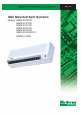
MWM - 2004 Wall Mounted Split Systems Models: MWM 007F/FR MWM 010F/FR MWM 015F/FR MWM 020F/FR MWM 025F/FR MWM 031F/030FR MWMV 010FR
Contents Special Features .................................................................................................... 1 Specifications......................................................................................................... 3 Performance Table................................................................................................ 14 Noise Level ............................................................................................................ 32 Operating Range ....
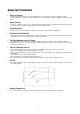
Special Features • Easy Installation - The wall mounted fan coil unit is easily installed because of its compact size, slimness and light weight. - Slim and short outdoor unit can be easily installed even in a narrow balcony and passageway and yet have a stable profile. • Space Saving - No space is required on either floor or ceiling. This newly developed super slim design for wall mounting maximises floor space usage and enhance ceiling appearance where ceilings are low.
Inverter Special Features • Energy Saving - Able to operate in wide range of frequency. - Regulate capacity according to load. • Precise Temperature Control - Modulate the compressor speed according to load. - Hence, provide more precise or stable temperature. - Less On/Off cycle. • Dry Mode - Super low speed of indoor fan and low running frequency of compressor can achieve more affective moisture removal. • Pre-Heat Function - To keep the compressor warm when the outdoor temperature is cold.
Specifications R22 MODELS (COOLING ONLY) MODEL INDOOR UNIT OUTDOOR UNIT NOMINAL COOLING CAPACITY INPUT POWER (W) - 1∅ [3∅] RUNNING CURRENT (A) - 1∅ [3∅] POWER SOURCE REFRIGERANT / CONTROL FAN TYPE AIR FLOW FAN FAN MOTOR RATED INPUT POWER (W) RATED RUNNING CURRENT (A) COIL FIN INDOOR UNIT TUBE FAN MOTOR PROTECTION MATERIAL TUBE PATTERN DIAMETER THICKNESS MATERIAL THICKNESS ROW FIN PER INCH FACE AREA HEIGHT DIMENSION WIDTH DEPTH WEIGHT SOUND PRESSURE LEVEL - H / M / L ROOM TEMPERATURE CONTROL AIR DIS
R22 MODELS (COOLING ONLY) MODEL COIL FIN INDOOR UNIT TUBE FAN NOMINAL COOLING CAPACITY INPUT POWER RUNNING CURRENT POWER SOURCE REFRIGERANT / CONTROL FAN TYPE AIR FLOW FAN MOTOR RATED INPUT POWER RATED RUNNING CURRENT FAN MOTOR PROTECTION MATERIAL TUBE PATTERN DIAMETER THICKNESS MATERIAL THICKNESS ROW FIN PER INCH FACE AREA HEIGHT DIMENSION WIDTH DEPTH WEIGHT SOUND PRESSURE LEVEL - H/M/L ROOM TEMPERATURE CONTROL AIR DISCHARGE OPERATION CONDENSATE DRAIN SIZE AIR FILTER PACKING HEIGHT DIMENSION WIDTH DE
R22 MODELS ( C SERIES) (COOLING ONLY) INDOOR UNIT OUTDOOR UNIT MODEL NOMINAL COOLING CAPACITY COIL FIN INDOOR UNIT TUBE FAN INPUT POWER RUNNING CURRENT POWER SOURCE REFRIGERANT / CONTROL FAN TYPE AIR FLOW FAN MOTOR RATED INPUT POWER RATED RUNNING CURRENT FAN MOTOR PROTECTION MATERIAL TUBE PATTERN DIAMETER THICKNESS MATERIAL THICKNESS ROW FIN PER INCH FACE AREA HEIGHT DIMENSION WIDTH DEPTH WEIGHT SOUND PRESSURE LEVEL- H / M / L ROOM TEMPERATURE CONTROL AIR DISCHARGE OPERATION CONDENSATE DRAIN SIZE AI
R22 MODELS (HEATPUMP) MODEL INDOOR UNIT OUTDOOR UNIT NOMINAL COOLING CAPACITY NOMINAL HEATING CAPACITY INPUT POWER (W) 1∅ [3∅] RUNNING CURRENT (A) 1∅ [3∅] COOLING HEATING COOLING HEATING POWER SOURCE REFRIGERANT / CONTROL FAN TYPE AIR FLOW FAN FAN MOTOR RATED INPUT POWER (W) RATED RUNNING CURRENT (A) COIL FIN INDOOR UNIT TUBE FAN MOTOR PROTECTION MATERIAL TUBE PATTERN DIAMETER THICKNESS MATERIAL THICKNESS ROW FIN PER INCH FACE AREA HEIGHT DIMENSION WIDTH DEPTH WEIGHT SOUND PRESSURE LEVEL - H / M
R22 MODELS (HEATPUMP) MODEL MWM030FR INDOOR UNIT OUTDOOR UNIT kcal/h W Btu/h kcal/h W Btu/h W (50/60Hz) W (50/60Hz) A (50/60Hz) A (50/60Hz) V/Ph/Hz cfm / L/s W (50/60Hz) A (50/60Hz) COIL mm/in mm/in mm/in FIN INDOOR UNIT TUBE FAN NOMINAL COOLING CAPACITY NOMINAL HEATING CAPACITY INPUT POWER (COOLING) - 1∅ [3∅] INPUT POWER (HEATING) - 1∅ [3∅] RUNNING CURRENT(COOLING) - 1∅ [3∅] RUNNING CURRENT (HEATING) - 1∅ [3∅] POWER SOURCE REFRIGERANT / CONTROL FAN TYPE AIR FLOW FAN MOTOR RATED INPUT POWER RATED
R22 MODELS (HEATPUMP) MODELS NOMINAL COOLING CAPACITY NOMINAL HEATING CAPACITY LOW TEMPERATURE HEATING CAPACITY INPUT POWER (W) RUNNING CURRENT (A) INDOOR UNIT OUTDOOR UNIT kcal/h W Btu/h kcal/h W Btu/h kcal/h W Btu/h COOLING HEATING COOLING HEATING COIL INDOOR UNIT COMP FIN TUBE FAN POWER SOURCE (V/Ph/Hz) REFRIGERANT FAN TYPE AIR FLOW (cfm / L/s) FAN MOTOR INPUT POWER (W) RUNNING CURRENT (A) FAN MOTOR PROTECTION MATERIAL DIAMETER (mm/in) THICKNESS (mm/in) MATERIAL THICKNESS (mm/in) ROW FIN PER INCH
R22 MODELS (C SERIES) (HEATPUMP) INDOOR UNIT OUTDOOR UNIT MODEL NOMINAL COOLING CAPACITY NOMINAL HEATING CAPACITY COIL mm/in mm/in mm/in 2 2 m /ft mm/in mm/in mm/in kg dBA mm/in mm/in A (50 Hz) W (50 Hz) W(50 Hz) FIN COIL TUBE COMPRESSOR mm/in mm/in mm/in V/Ph/Hz FAN FIN cfm / L/s 50 Hz W (50 Hz) A (50 Hz) µF A A W W A PIPE OUTDOOR UNIT INDOOR UNIT TUBE FAN INPUT POWER (COOLING) INPUT POWER (HEATING) RUNNING CURRENT (COOLING) RUNNING CURRENT (HEATING) POWER SOURCE REFRIGERANT / CONT
R407C MODELS (COOLING ONLY) COIL FIN TUBE FIN COIL PIPE OUTDOOR UNIT FAN COMPRESSOR INDOOR UNIT TUBE FAN MODEL INDOOR UNIT OUTDOOR UNIT NOMINAL COOLING CAPACITY INPUT POWER 1∅ [ 3∅ ] RUNNING CURRENT 1∅ [ 3∅ ] POWER SOURCE REFRIGERANT / CONTROL AIR FLOW FAN MOTOR RATED INPUT POWER RATED RUNNING CURRENT FAN MOTOR PROTECTION MATERIAL DIAMETER THICKNESS MATERIAL THICKNESS ROW FIN PER INCH FACE AREA HEIGHT DIMENSION WIDTH DEPTH WEIGHT SOUND PRESSURE LEVEL ROOM TEMPERATURE CONTROL AIR DISCHARGE OPERATIO
R407C MODELS (COOLING ONLY) MODEL INDOOR UNIT OUTDOOR UNIT TUBE COIL FIN INDOOR UNIT COMPRESSOR TUBE FAN FIN COIL OUTDOOR UNIT PIPE MWM031F M4LC031C 7308 8499 29000 2854 [ 2854 ] 13.1 [ 4.9 ] 220 - 240 / 1 / 50 R407C / OUTDOOR CAPILLARY TUBE ANTI FUNGUS CROSS FLOW FAN 740 / 349 4 POLES X 45W 71 0.30 THERMAL OVERLOAD RELAY SEAMLESS COPPER TUBE INNER GROOVED 9.52 / 0.375 0.35 / 0.013 ALUMINIUM (HYDROPHILIC SLIT FIN TYPE) 0.11 / 0.0043 2 16 0.291 / 3.130 360 / 14.2 1200 / 47.2 200 / 7.
R407C MODELS (HEATPUMP) INDOOR UNIT OUTDOOR UNIT NOMINAL COOLING CAPACITY NOMINAL HEATING CAPACITY INPUT POWER COOLING HEATING 1∅ [ 3∅ ] RUNNING CURRENT COOLING HEATING 1∅ [ 3∅ ] POWER SOURCE REFRIGERANT / CONTROL AIR FLOW FAN MOTOR RATED INPUT POWER RATED RUNNING CURRENT FAN MOTOR PROTECTION MATERIAL DIAMETER THICKNESS MATERIAL THICKNESS ROW FIN PER INCH FACE AREA HEIGHT DIMENSION WIDTH DEPTH WEIGHT SOUND PRESSURE LEVEL ( H / M / L ) ROOM TEMPERATURE CONTROL AIR DISCHARGE OPERATION CONDENSATE DRAIN SIZE AI
R407C MODELS (HEATPUMP) INDOOR UNIT OUTDOOR UNIT NOMINAL COOLING CAPACITY NOMINAL HEATING CAPACITY INPUT POWER (COOLING) - 1∅ [ 3∅ ] INPUT POWER (HEATING) - 1∅ [ 3∅ ] RUNNING CURRENT(COOLING) - 1∅ [ 3∅ ] RUNNING CURRENT (HEATING) - 1∅ [ 3∅ ] POWER SOURCE REFRIGERANT / CONTROL FAN TYPE AIR FLOW FAN MOTOR RATED INPUT POWER RATED RUNNING CURRENT FAN MOTOR PROTECTION MATERIAL TUBE PATTERN DIAMETER THICKNESS MATERIAL THICKNESS ROW FIN PER INCH FACE AREA HEIGHT DIMENSION WIDTH DEPTH WEIGHT SOUND PRESSURE LEVEL -
Performance Table R22 MODELS (COOLING ONLY) MODEL : MWM 007F / MLC 007B Indoor DB °C 26.7 Indoor WB °C 13.9 15 18 19.4 20 22 24 Capacity kW TC SC TC SC TC SC TC SC TC SC TC SC TC SC 19.4 2.525 2.525 2.594 2.413 2.784 2.110 2.872 1.968 2.910 1.907 3.036 1.705 3.162 1.502 25 2.331 2.331 2.395 2.243 2.570 2.003 2.651 1.891 2.691 1.832 2.826 1.634 2.961 1.436 Outdoor DB, ° C 30 35 2.157 1.984 2.157 1.984 2.217 2.038 2.090 1.938 2.378 2.187 1.908 1.813 2.454 2.257 1.823 1.755 2.497 2.302 1.765 1.698 2.
MODEL : MWM 020F / MLC 020B Indoor DB °C 26.7 Indoor WB °C 13.9 15 18 19.4 20 22 24 Capacity kW TC SC TC SC TC SC TC SC TC SC TC SC TC SC 19.4 5.161 4.729 5.399 4.479 6.047 3.797 6.350 3.479 6.480 3.343 6.912 2.889 7.344 2.434 25 4.907 4.565 5.139 4.350 5.774 3.761 6.069 3.486 6.183 3.347 6.563 2.884 6.943 2.420 30 4.680 4.420 4.908 4.234 5.529 3.728 5.819 3.492 5.919 3.351 6.252 2.879 6.586 2.407 Outdoor DB, ° C 35 40 46 4.453 4.030 3.738 4.274 3.868 3.588 4.676 4.232 3.925 4.119 3.728 3.458 5.285 4.
MODEL : MWM 031F / MLC 031C Indoor DB °C 26.7 Indoor WB °C 13.9 15 18 19.4 20 22 24 Capacity kW TC SC TC SC TC SC TC SC TC SC TC SC TC SC 19.4 8.060 7.613 8.539 7.299 9.845 6.443 10.455 6.044 10.716 5.872 11.587 5.302 12.458 4.731 25 7.677 7.325 8.113 7.038 9.303 6.258 9.858 5.894 10.091 5.717 10.868 5.126 11.644 4.536 30 7.336 7.067 7.734 6.806 8.819 6.093 9.325 5.761 9.533 5.578 10.225 4.970 10.917 4.362 Outdoor DB, ° C 35 40 46 6.994 6.659 6.309 6.809 6.483 6.142 7.354 7.001 6.633 6.573 6.204 5.
MODEL : MWM 007F / MLC 007C Indoor DB °C 26.7 Indoor WB °C 13.9 15 18 19.4 20 22 24 Capacity kW TC SC TC SC TC SC TC SC TC SC TC SC TC SC 19.4 2.580 2.580 2.600 2.416 2.654 1.970 2.680 1.762 2.691 1.673 2.727 1.376 2.763 1.078 25 2.357 2.357 2.383 2.231 2.453 1.888 2.486 1.728 2.504 1.645 2.563 1.367 2.622 1.089 Outdoor DB, ° C 30 35 2.157 1.958 2.157 1.958 2.188 1.994 2.065 1.900 2.273 2.093 1.815 1.741 2.313 2.140 1.698 1.667 2.336 2.169 1.619 1.594 2.416 2.269 1.359 1.350 2.495 2.369 1.098 1.
R22 MODELS (HEATPUMP – COOLING MODE) MODEL : MWM 007FR / MLC 007BR Indoor DB °C 26.7 Indoor WB °C 13.9 15 18 19.4 20 22 24 Capacity kW TC SC TC SC TC SC TC SC TC SC TC SC TC SC 19.4 2.534 2.534 2.563 2.390 2.643 1.999 2.681 1.817 2.697 1.738 2.750 1.478 2.804 1.217 25 2.338 2.338 2.376 2.227 2.480 1.925 2.529 1.784 2.548 1.709 2.613 1.458 2.678 1.206 Outdoor DB, ° C 30 35 2.162 1.987 2.162 1.987 2.208 2.041 2.081 1.935 2.334 2.188 1.859 1.793 2.393 2.257 1.756 1.727 2.415 2.282 1.683 1.657 2.490 2.
MODEL : MWM 020FR / MLC 020BR Indoor DB °C 26.7 Indoor WB °C 13.9 15 18 19.4 20 22 24 Capacity kW TC SC TC SC TC SC TC SC TC SC TC SC TC SC 19.4 4.719 4.632 5.264 4.563 6.750 4.376 7.443 4.288 7.740 4.251 8.731 4.126 9.722 4.001 25 4.558 4.489 5.000 4.397 6.207 4.146 6.770 4.029 7.038 3.982 7.929 3.824 8.820 3.666 30 4.414 4.362 4.765 4.249 5.723 3.941 6.169 3.798 6.410 3.742 7.213 3.554 8.016 3.367 Outdoor DB, ° C 35 40 46 4.270 3.865 3.584 4.234 3.832 3.554 4.530 4.100 3.802 4.101 3.711 3.442 5.
MODEL : MWM 030FR / MLC 030CR Indoor DB °C 26.7 Indoor WB °C 13.9 15 18 19.4 20 22 24 Capacity kW TC SC TC SC TC SC TC SC TC SC TC SC TC SC 19.4 7.491 7.444 8.152 6.887 9.955 5.368 10.796 4.659 11.156 4.355 12.358 3.343 13.560 2.330 25 7.228 7.191 7.798 6.734 9.352 5.487 10.077 4.906 10.395 4.605 11.454 3.603 12.514 2.600 30 6.994 6.965 7.482 6.597 8.813 5.594 9.435 5.126 9.714 4.828 10.647 3.835 11.579 2.841 Outdoor DB, ° C 35 40 46 6.759 6.435 6.097 6.740 6.416 6.079 7.166 6.822 6.464 6.461 6.151 5.
MODEL : MWM 007FR / MLC 007CR Indoor DB °C 26.7 Indoor WB °C 13.9 15 18 19.4 20 22 24 Capacity kW TC SC TC SC TC SC TC SC TC SC TC SC TC SC 19.4 2.492 2.492 2.533 2.351 2.646 1.965 2.699 1.785 2.721 1.708 2.796 1.451 2.872 1.195 25 2.305 2.305 2.352 2.199 2.480 1.912 2.540 1.778 2.565 1.702 2.648 1.448 2.731 1.194 Outdoor DB, ° C 30 35 2.137 1.970 2.137 1.970 2.190 2.027 2.064 1.929 2.332 2.184 1.865 1.817 2.398 2.257 1.772 1.765 2.425 2.286 1.696 1.690 2.516 2.383 1.445 1.442 2.606 2.481 1.194 1.
R22 MODELS (HEATPUMP – HEATING MODE) MODEL : MWM 007FR / MLC 007BR (HEATING MODE) -9.0 -5.0 6.0 12.0 15.0 18.3 kW 15.0 17.0 19.0 21.0 24.0 26.7 TC 1.322 1.302 1.283 1.263 1.257 1.252 SC 1.322 1.302 1.283 1.263 1.257 1.252 TC 1.565 1.551 1.537 1.523 1.502 1.483 SC 1.565 1.551 1.537 1.523 1.502 1.483 TC 2.233 2.270 2.308 2.345 2.225 2.117 SC 2.233 2.270 2.308 2.345 2.225 2.117 TC 2.598 2.575 2.551 2.528 2.494 2.462 SC 2.598 2.575 2.551 2.528 2.
MODEL : MWM 020FR / MLC 020BR (HEATING MODE) -9.0 -5.0 6.0 12.0 15.0 18.3 kW 15.0 17.0 19.0 21.0 24.0 26.7 TC 3.686 3.651 3.616 3.581 3.535 3.493 SC 3.686 3.651 3.616 3.581 3.535 3.493 TC 4.254 4.216 4.178 4.140 4.083 4.031 SC 4.254 4.216 4.178 4.140 4.083 4.031 TC 5.816 5.832 5.847 5.862 5.678 5.513 SC 5.816 5.832 5.847 5.862 5.678 5.513 TC 6.668 6.609 6.550 6.490 6.401 6.320 SC 6.668 6.609 6.550 6.490 6.401 6.320 TC 7.094 7.031 6.968 6.
MODEL : MWM 030FR / MLC 030CR (HEATING MODE) -9.0 kW 15.0 17.0 19.0 21.0 24.0 26.7 TC 5.513 5.513 6.365 6.365 8.709 8.709 9.987 9.987 10.626 10.626 11.329 11.329 5.460 5.460 6.308 6.308 8.737 8.737 9.898 9.898 10.531 10.531 11.228 11.228 5.407 5.407 6.251 6.251 8.765 8.765 9.809 9.809 10.437 10.437 11.127 11.127 5.355 5.355 6.194 6.194 8.792 8.792 9.720 9.720 10.342 10.342 11.026 11.026 5.285 5.285 6.108 6.108 8.509 8.509 9.586 9.586 10.200 10.200 10.875 10.875 5.223 5.223 6.031 6.031 8.
MODEL : MWM 007FR / MLC 007CR (HEATING MODE) -9.0 -5.0 6.0 12.0 15.0 18.3 kW 15.0 17.0 19.0 21.0 24.0 26.7 TC 1.863 1.870 1.877 1.884 1.821 1.765 SC 1.863 1.870 1.877 1.884 1.821 1.765 TC 2.009 1.991 1.973 1.955 1.928 1.904 SC 2.009 1.991 1.973 1.955 1.928 1.904 TC 2.411 2.340 2.269 2.198 2.244 2.285 SC 2.411 2.340 2.269 2.198 2.244 2.285 TC 2.631 2.607 2.584 2.560 2.525 2.493 SC 2.631 2.607 2.584 2.560 2.525 2.493 TC 2.740 2.716 2.691 2.
R407C MODELS (COOLING ONLY) MODEL : MWM 007F / M4LC 007B Indoor DB °C 26.7 Indoor WB °C 13.9 15 18 19.4 20 22 24 Capacity KW TC SC TC SC TC SC TC SC TC SC TC SC TC SC 19.4 2.428 2.428 2.494 2.321 2.676 2.029 2.761 1.892 2.798 1.834 2.919 1.639 3.040 1.445 25 2.241 2.241 2.303 2.156 2.471 1.926 2.549 1.819 2.588 1.761 2.717 1.571 2.847 1.381 Outdoor DB, ° C 30 35 2.074 1.907 2.074 1.907 2.131 1.960 2.010 1.863 2.287 2.103 1.835 1.743 2.359 2.170 1.753 1.687 2.400 2.213 1.697 1.632 2.537 2.357 1.510 1.
MODEL : MWM 020F / M4LC 020B Indoor DB °C 26.7 Indoor WB °C 13.9 15 18 19.4 20 22 24 Capacity kW TC SC TC SC TC SC TC SC TC SC TC SC TC SC 19.4 4.970 4.554 5.199 4.313 5.824 3.657 6.115 3.351 6.240 3.219 6.656 2.782 7.073 2.344 25 4.725 4.396 4.949 4.189 5.560 3.622 5.845 3.357 5.955 3.223 6.321 2.777 6.687 2.330 30 4.507 4.256 4.726 4.078 5.325 3.591 5.604 3.363 5.700 3.227 6.021 2.772 6.342 2.318 Outdoor DB, ° C 35 40 46 4.288 3.881 3.600 4.116 3.725 3.455 4.503 4.076 3.780 3.967 3.590 3.330 5.
R407C MODELS (HEATPUMP – COOLING MODE) MODEL : MWM 007FR / M4LC 007BR Indoor DB °C 26.7 Indoor WB °C 13.9 15 18 19.4 20 22 24 Capacity KW TC SC TC SC TC SC TC SC TC SC TC SC TC SC 19.4 2.501 2.501 2.530 2.359 2.609 1.973 2.646 1.793 2.662 1.716 2.714 1.458 2.767 1.201 25 2.307 2.307 2.345 2.198 2.448 1.900 2.496 1.761 2.515 1.687 2.579 1.439 2.643 1.191 Outdoor DB, ° C 30 35 2.134 1.962 2.134 1.962 2.180 2.015 2.054 1.910 2.304 2.160 1.835 1.770 2.362 2.227 1.733 1.705 2.384 2.253 1.661 1.635 2.458 2.
MODEL : MWM 020FR / M4LC 020BR Indoor DB °C 26.7 Indoor WB °C 13.9 15 18 19.4 20 22 24 Capacity kW TC SC TC SC TC SC TC SC TC SC TC SC TC SC 19.4 4.346 4.266 4.848 4.202 6.216 4.030 6.855 3.949 7.129 3.915 8.041 3.800 8.954 3.685 25 4.198 4.134 4.605 4.050 5.717 3.819 6.235 3.711 6.482 3.667 7.303 3.522 8.124 3.376 30 4.065 4.017 4.389 3.913 5.270 3.630 5.682 3.498 5.904 3.446 6.643 3.274 7.382 3.101 Outdoor DB, ° C 35 40 46 3.933 3.559 3.301 3.900 3.529 3.273 4.172 3.776 3.502 3.777 3.418 3.170 4.
R407C MODELS (HEATPUMP – HEATING MODE) MODEL : MWM 007FR / M4LC 007BR (HEATING MODE) -9.0 -5.0 6.0 12.0 15.0 18.3 kW 15.0 17.0 19.0 21.0 24.0 26.7 TC 1.222 1.204 1.186 1.168 1.163 1.158 SC 1.222 1.204 1.186 1.168 1.163 1.158 TC 1.447 1.434 1.421 1.408 1.389 1.371 SC 1.447 1.434 1.421 1.408 1.389 1.371 TC 2.066 2.100 2.134 2.169 2.058 1.958 SC 2.066 2.100 2.134 2.169 2.058 1.958 TC 2.403 2.382 2.360 2.339 2.307 2.278 SC 2.403 2.382 2.360 2.
MODEL : MWM 020FR / M4LC 020BR (HEATING MODE) -9.0 -5.0 6.0 12.0 15.0 18.3 kW 15.0 17.0 19.0 21.0 24.0 26.7 TC 3.502 3.469 3.436 3.402 3.358 3.318 SC 3.502 3.469 3.436 3.402 3.358 3.318 TC 4.042 4.005 3.969 3.933 3.879 3.830 SC 4.042 4.005 3.969 3.933 3.879 3.830 TC 5.526 5.540 5.554 5.569 5.394 5.237 SC 5.526 5.540 5.554 5.569 5.394 5.237 TC 6.335 6.279 6.222 6.166 6.081 6.004 SC 6.335 6.279 6.222 6.166 6.081 6.004 TC 6.740 6.680 6.
Noise Level Sound Pressure Level (Measured In Anechoic Room) Wall Mounted Fan Coil Unit 240V/50Hz/1PH Model MWM007F/FR MWMV010FR MWM010F/FR MWM015F/FR MWM020F/FR MWM025F/FR MWM031F MWM030FR Speed High Medium Low High Medium Low High Medium Low High Medium Low High Medium Low High Medium Low 125Hz 35 27 27 35 32 28 35 33 31 39 37 34 41 38 36 42 40 37 1/1 Octave Sound pressure level (dB, ref 20µPa) 250Hz 500Hz 1kHz 2kHz 4kHz 34 36 35 31 24 28 30 28 22 16 25 28 25 20 15 34 36 35 31 24 29 32 29 25 18 26
MWM007F/FR NC CURVES (240V, 50Hz) MWM010F/FR NC CURVES (240V, 50Hz) 33
MWM015F/FR NC CURVES (240V, 50Hz) MWM020F/FR NC CURVES (240V, 50Hz) 34
MWM025F/FR NC CURVES (240V, 50Hz) MWM031F/ 030FR NC CURVES (240V, 50Hz) 35
Operating Range Ensure the operating temperature is in allowable range. Cooling only Cooling Caution : Outdoor temp. (°CDB) 54 HIGH AMBIENT UNIT 46 The use of your air conditioner outside the range of working temperature and humidity can result in serious failure. 35 STD 19 LOW AMBIENT KIT -5 15 24 Indoor temp. (°CWB) Heat pump Heating Cooling 54 Outdoor temp. (°CDB) Outdoor temp. (°CWB) 18 6 STD -9 HIGH AMBIENT UNIT 46 35 STD 19 LOW AMBIENT KIT -5 15 21 15 27 24 Indoor temp.
Refrigeration Cycle Diagram Cooling Only Models Model : MLC/M4LC 007B / 010B / 015B / 020B MLC 007C / 010C / 015C Model : MLC/M4LC 025B, MLC 031B 37
Model : MLC / M4LC 031C 38
Heatpump Models Model : MLC / M4LC 007BR / 010BR, MLC 010CR Model : MLC 007CR 39
Model : MLCV 010BR Model : MLC / M4LC 015BR 40
Model : MLC 015CR Model : MLC /M4LC 020BR 41
Model : MLC / M4LC 025BR, MLC 030BR Model : MLC / M4LC 030CR 42
Outlines And Dimensions Indoor Unit Model: MWM 007F / 007FR / 010F / 010FR / 015F / 015FR, MWMV 010FR Note : Dimension in mm Outdoor Unit Model : MLC 007B / 007BR / 010B / 010BR / 015B / 015BR M4LC 007B / 007BR / 010B / 010BR / 015B / 015BR, MLCV 010BR Note : Dimension in mm 43
Indoor Unit Model : MWM 020F / 020FR / 025F / 025FR Note : Dimension in mm Outdoor Unit Model : MLC 020B / 020BR / 025B / 025BR / 031B / 030BR M4LC 020B / 020BR / 025B / 025BR Note : Dimension in mm 44
Indoor Unit Model : MWM 031F/030FR Outdoor Unit Model : MLC 031C, MLC 030CR M4LC 031C, M4LC 030CR 45
Indoor Unit Model: MWM 007F / 007FR Note : Dimension in mm Outdoor Unit Model : MLC 007C / 007CR Note : Dimension in mm 46
Indoor Unit Model: MWM 010F / 010FR / 015F / 015FR Note : Dimension in mm Outdoor Unit Model : MLC 010C / 010CR / 015C / 015CR Note : Dimension in mm 47
Wiring Diagrams Cooling Only Models Indoor Unit Model : MWM 007F / 010F / 015F (D2.0 I.C.
Cooling Only Models Indoor Unit Model : MWM 020F / 025F (D2.0 I.C.
Cooling Only Models Indoor Unit Model : MWM 020F / 025F (D2.0 I.C.
Cooling Only Models Outdoor Unit Model : MLC 031B Indoor Unit Model : MWM 031F (D2.0 I.C.
Cooling Only Models Indoor Unit Model : MWM 031F (D2.0 I.C.
Cooling Only Models Indoor Unit Model : MWM 031F (D2.0 I.C.
Cooling Only Models Indoor Unit Model : MWM 007F / 015F (D2.0 I.C.
Cooling Only Models Indoor Unit Model : MWM 010F (D2.0 I.C.
Heatpump Models Indoor Unit Model : MWM 007FR / 010FR / 015FR (U1.4 I.C.
Heatpump Models Indoor Unit Model : MWMV 010FR (INV1A I.C.
Heatpump Models Indoor Unit Model : MWM 020FR / 025FR (U1.4 I.C.
Heatpump Models Indoor Unit Model : MWM 020FR / 025FR (U1.4 I.C.
Heatpump Models Indoor Unit Model : MWM 030FR (U1.4 I.C.
Heatpump Models Indoor Unit Model : MWM 030FR (U1.4 I.C.
Heatpump Models Indoor Unit Model : MWM 030FR (U1.4 I.C.
Heatpump Models Indoor Unit Model : MWM 007FR / 015FR (U1.4 I.C.
Heatpump Models Indoor Unit Model : MWM 010FR (U1.4 I.C.
High Ambient Unit (Optional) Cooling Only Models Outdoor Unit Model : MLC 020B / 025B 50Hz / 1 Phase / 220 – 240V 60Hz / 1 Phase / 208 – 230V Outdoor Unit Model : MLC 031C 50Hz / 1 Phase / 220 – 240V, 60Hz / 1 Phase / 208 – 230V 65
High Ambient Unit (Optional) Heatpump Models Outdoor Unit Model : MLC 020BR / 025BR 50Hz / 1 Phase / 220 – 240V Outdoor Unit Model : MLC 030CR 50Hz / 1 Phase / 220 – 240V 60 Hz / 1 Phase / 220V 66
Low Ambient Unit (Optional) Cooling Only Models Outdoor Unit Model : MLC 010B / 015B 50Hz / 1 Phase / 220~240V Outdoor Unit Model : MLC 020B / 025B 50Hz / 1 Phase / 220~240V 67
Low Ambient Unit (Optional) Heatpump Models Outdoor Unit Model : MLC 010BR / 015BR 50Hz / 1 Phase / 220 – 240V Outdoor Unit Model : MLC 020BR 50Hz / 1 Phase / 220 – 240V Outdoor Unit Model : MLC 025BR 50Hz / 1 Phase / 220 – 240V 68
Safety Precautions Before Installation Before operating, please read the following "Safety Precautions" carefully. To prevent injury to the user or other people and properties damage, the following instructions must be followed. § Incorrect operation due to ignoring of instruction will cause harm or damage, the seriousness is classified by the following indications. Warning: This sign indicates the possibility of causing death or serious injury.
Symbol (with white background) denotes item that is PROHIBITED from doing. Symbol (with black background) denotes item that is COMPULSORY to be carried out. Caution Please confirm the following important points when installation • Grounding is necessary It may cause electrical shock if grounding is not perfect. • Do not install the unit where leakage of flammable gas may occur In case of gas leaks and accumulates at the surrounding of the unit, it may cause fire ignition.
Special Precautions For R407C Special precautions when dealing with refrigerant R407C unit 1) What is new refrigerant R407C? R407C is a zeotropic refrigerant mixture which has Zero Ozone Depletion Potential (ODP = 0) and thus conformed to the Montreal Protocol regulation. It requires Polyol-ester oil (POE) oil for its compressor's lubricant. Its refrigerant capacity and performance are about the same as the refrigerant R22.
c) Ensure that the compressor is not expose to open air for more than the recommended time specified by its manufacturer (typically less than 10 minutes). Removed the seal-plugs only when the compressor is about to be brazed. d) The system should be thoroughly vacuumed to 1.0 Pa (-700mmHg) or lower. This vacuuming level is more stringent than R22 system so as to ensure no incompressible gas and moisture in the system.
Installation Installation diagram 73
CAUTION: Before installing the unit, ensure that the power supply matches the power requirement of the air conditioner. 1) Selection Of Location And Space (A) Indoor Unit Install the fan coil (indoor) unit at a location with the following requirements • Location is suitable for wiring, piping and drainage. • No obstruction of air flow into and out of unit where cooler air can be evenly distributed.(See fig. 1) • Ensure that air discharge is not short circuited with air intake.
(B) Outdoor unit As condensing temperature rises, evaporating temperature rises and cooling capacity drops. In order to achieve maximum cooling capacity, the location selected for outdoor unit should fulfill the following requirements : • Install the condensing (outdoor) unit in a way such that hot air distributed by the outdoor condensing unit cannot be drawn in again (as in the case of short circuit of hot discharge air). Allow sufficient space for maintenance around the unit.
Condensed Water Disposal Of Outdoor Unit (Heatpump Unit Only) • There are 2 holes on the base of outdoor unit for condensed water to flow out. Insert the drain elbow to one of the holes. • To install the drain elbow, first insert one portion of the hook to the base (portion A), then pull the drain elbow in the direction shown by the arrow while inserting the other portion to the base. After installation, check to ensure that the drain elbow clings to base firmly.
2) Drilling Holes And Mounting Installation Plate CAUTION: i) Please check the unit weight for each model. Always ensure that the wall is sufficiently strong to withstand the weight. If not, it is necessary to reinforce the wall with plate, beams or pillars. ii) The unit cannot be directly fixed onto the wall or the likes. In all cases, the installation plate provided MUST be used. • Paste the installation plan provided on the desired location on the wall and mark the holes location accordingly.
3) Indoor Unit Preparation • • The refrigerant piping can be routed to the unit in 5 direction, by using the cut outs in the unit casing. (See fig. 1) Carefully bend the pipes to the required position to align with the hole. For right hand and rear side draw out, hold the bottom of the piping and fix direction before shaping it to the desired position (See fig. 2). The condensation drain hose should be taped to the pipes with vinyl tape. The electrical cable can also be taped to the pipes.
5) Water Drainage Piping The indoor drain pipe must be downward gradient for smooth drainage. Avoid situation as shown in figure below. 6) Wiring Electrical Connection • Wiring regulation on wire diameters differ from country to country. Please refer to your LOCAL ELECTRICAL CODES for field wiring rules. Be sure that installation comply with such rules and regulations.
7) Refrigerant Piping Maximum Pipe Length And Maximum Number Of Bends Always choose the shortest path for refrigerant piping and follow the recommendations as tabulated below: MODEL DATA MWM031F MWM030FR MWM MWM MWM MWM MWM 007F/FR 010F/FR 015F/FR 020F/FR 025F/FR MLC031B MLC031C* MLC030BR MLC030CR Max. Length, L (m) 12 12 12 15 15 35 45 35 45 Max. Elevation, H (m) 5 5 5 8 8 15 25 15 25 Max. No.
4) After evacuation, unscrew the spindle (diagram B) for the gas to run to indoor unit. 5) Decision by low side pressure. Turn compressor on for 10 or 15 min. STANDARD CONDITION HEAVY LOAD CONDITION Indoor 27°C/ Outdoor 35°C Indoor 32°C/ Outdoor 43°C kg/cm 2 psig kg/cm 2 psig MWM 007F/FR 5.2 ~ 6.0 74.0 ~ 85.0 5.7 ~ 6.4 81.0 ~ 92.0 MWM 010F/FR 5.2 ~ 6.0 74.0 ~ 85.0 5.7 ~ 6.4 81.0 ~ 92.0 MWM 015F/FR 4.6 ~ 5.6 65.4 ~ 79.6 5.2 ~ 6.3 74.0 ~ 89.6 MWM 020F/FR 4.6 ~ 5.6 65.4 ~ 79.6 5.
Diagram shows typical charging method. Note : R407C – Fix filter dryer R22 - Nil CAUTION FOR R407C Avoid prolong exposure of an opened compressor, or the internal part of refrigerant piping to moist air. The POE oil in the compressor and piping can absorb moisture from air. 9) Final Checking • Ensure that steps 1 to 8 are closely followed. • Ensure the following, in particular : 1) The unit is mounted solidly and rigidly in position. 2) Piping and connections are leak proof after charging.
Remote Controller Operation Guide G7 Remote Controller 1 2 .Transmission source • 4 • 3 Temperature setting • • • Signal Transmission indication The source where the signal will be transmitted. To set the desired room temperature, press the button to increase or decrease the set temperature. The temperature setting range is from 16°C to 30°C (Optional setting 18°C to 30°C). Press both buttons simultaneously to toggle the temperature setting between °C and °F.
INDICATOR LIGHTS (cooling only unit) IR signal receiver When there is infrared remote control operating signal, the signal receiver on indoor unit will made a (beep) for signal acceptance confirmation. LED Indicator Lights The table below shows the LED indicator light for air conditioner unit under normal operation and fault condition. The LED indicator lights are located at the right bottom of the air conditioner unit.
Heatpump unit : LED Indicator Lights Display Cooling mode (Green) Dry mode (Orange) Heat/Fan mode (Red/Green) Sleep mode (Red) The heat pump units is equipped with an "auto" mode, whereby the unit will provide reasonable room temperature by switching the unit automatically to either "cool" mode or "heat" mode, according to the temperature setting set by the user.
Special Function (A) 3 Hot System (Heating cycle) a) Hot start At the beginning of heating operation (cold start, after defrosting or thermostat resumes operation) the indoor fan operation is controlled in accordance with the temperature of the indoor heat exchanger to send warm air from the start. 18°C b) Hot keep After thermostat cut out, the indoor fan operation is controlled in accordance with the indoor heat exchanger temperature to utilize the extra heat and preserve indoor comfort.
“Hot Keep” (Inverter only) RUN COMP & OF STOP SET AIR FLOW L LOSLO STOP INDOOR COIL TEMP. 38°C 32°C 10°C 27°C “Hot Start” (Inverter Only) Indoor fan SLo Indoor fan off 14°C 10°C 30°C Indoor fan L Indoor fan Lo- 25°C 18°C Set air flow Indoor fan L 22°C Indoor fan SLo INDOOR COIL TEMP. Indoor fan Lo- 38°C Set air flow 30°C c) Hot spurt o During cold start, the set temperature of controller is increased by 2 C to stabilize the room temperature quickly.
(B) Cold Blast (Cooling cycle) During cold start, the set temperature of controller is decreased by 2°C to stabilize the room temperature quickly. (C) Overload Prevention In Heating Operation During heating operation, if the room temperature and outdoor temperature are high, or when the indoor air filter is choked, the condensing pressure will increase rapidly. To prevent the burn out of compressor, the M. C. controller will stop the operation of the air conditioner under this condition. COMP.
Servicing And Maintenance CAUTION: After installing or servicing the unit, please ensure that the front panel is secured by the 1 hook underneath the front panel. The unit is designed to give a long life operation with minimum maintenance required. However, it should be regularly checked and the following items should be given due attention. Components Maintenance Procedure Recommended Schedule Air Filters 1 .
Pre-start up maintenance (After extended shutdown) - Inspect thoroughly and clean indoor and outdoor units. Clean or replace air filters. Clean condensate drain line. Clean clogged indoor and outdoor coils. Check fan imbalance before operation. Tighten all wiring connections and panels. Check for refrigerant leakage. The design of the MLC outdoor series allows servicing to be carried out readily and easily. The removal of the top side, front and back panel make almost every part accessible.
Troubleshooting By means of pressure readings : High Side Low Side High Side Low Side High Side Low Side Too High A Little High Circuit PROBABLE CAUSE Normal Too Low Data A Little Low PRESSURE = = = = = = = High Side Low Side = = High Side Low Side 1. Overcharged with refrigerant. 2. Non-condensable gases in refrigerant circuit (e.g. oil). 3. Obstructed air-intake/discharge. 4. Short circuiting of hot air at condensing unit. 1. Poor compression/no compression (compressor defective.) 2.
The most common causes of air conditioner failure to "start" are : a) Voltage not within +/- 10% of rated voltage. b) Power supply interrupted. c) Control settings improper d) Air Conditioner is disconnected from main power source. e) Fuse blown or circuit breaker off. ii) Diagnosis Of Refrigerant Circuit /Application There might be some cases where the unit starts running but does not perform satisfactory, i.e. insufficient cooling.
Parts List Indoor Unit Model: MWM 007F / 007FR / 010F / 010FR / 015F / 015FR MWMV 010FR 10 1. ASSY. MOUNTING PLATE 10. BUSH, FAN 2. CLAMP. PIPING 11. ASSY. EVAPORATOR COIL 3. ASSY. CHASIS 12. ASSY. FRONT FRAME A 4. ASSY. FAN MOTOR 13. WASHER, INT TEETH STAR 5. ASSY. CONTROL BOX 14. SCREW, PAN HEAD MACHINED 6. ASSY. COVER CONTROL BOX 15. SCREW, SELF TAPPING ROUND HEAD 7. ASSY. AIR DISCHARGE HOUSING 16. SCREW, SELF TAPPING PAN HEAD 8. RIVET 9.
Model : MWM 020F / 020FR / 025F / 025FR / 031F/ 030FR 1. ASSY. CHASIS 8. ASSY. EVAPORATOR COIL 2. PIPING, CLAMP 9. ASSY. AIR DISCHARGE HOUSING 3. ASSY. CONTROL BOX 10. CROSS FLOW FAN 4. ASSY. CONTROL BOX COVER 11. SCREW, SELF TAPPING ROUND HEAD 5. ASSY. MOUNTING PLATE 12. SCREW, SELF TAPPING PAN HEAD 6. ASSY. FAN MOTOR 13. WASHER, INT. TEETH STAR 7. ASSY. FRONT COVER 14.
Outdoor Unit Model: MLC 007B / 010B / 015B M4LC 007B / 010B / 015B 1. ASSY., BACK PANEL 14. ASSY., BASE PAN 2. ASSY., TOP PANEL 15. ASSY., CAPILLARY TUBE 3. ASSY., CONDENSER COIL 16. ASSY., PARTITION 4. BRACKET, MOTOR MOUNTING 17. ASSY., TERMINAL PANEL W/O CONT. 5. FAN MOTOR 18. ASSY., SIDE PANEL 6. FAN, 14” 19. PANEL, ACCESS 7. ASSY., FRONT PANEL 20. PLATE, FLARE VALVE 8. SCREW, FAN SET 21. VALVE, SUCTION 9. TUBE, SUCTION 22. VALVE, LIQUID 10. TUBE, DISCHARGE 23.
Model: MLC 020B / 025B / 031B M4LC 020B / 025B 1. ASSY., BACK PANEL 16. GROMMET, RUBBER 2. ASSY., TOP PANEL 17. NUT, WITH WASHER 3. ASSY., CONDENSOR COIL 18. ASSY., BASE PAN 4. BRACKET, MOTOR MOUNTING 19. ASSY., CAPILLARY TUBE 5. MOTOR, FAN 20. ASSY., PARTITION 6. FLINGER 21. ASSY., TERMINAL BOX PANEL W/O CONT. 7. WASHER, RING 22. ASSY., SIDE PANEL 8. FAN, 16” 23. ASSY., ACCESS PANEL 9. WASHER, SQUARE 24. PLATE, FLARE VALVE 10. HEX. NUT 25. VALVE, SUCTION 11. LABEL, BLACK 26.
Model: MLC / M4LC 031C 1. ASSY., BASE PAN 12. PANEL, BACK RIGHT 2. ASSY., COIL 13. ASSY., TERMINAL BOARD 3. ASSY., VAVLE PLATE 14. ASSY., FRONT PANEL 4. ASSY., COMPRESSOR 15. PANEL, SERVICE 5. ASSY., TUBE DISCHARGE 16. PANEL, TOP 6. ASSY., CAPILLARY TUBE 17. HANDLE 7. ASSY., PARTITION 18. TUBE, ACC. TO OUTLET VALVE 8. BRACKET, MOTOR 19. TUBE, COMP. SUCTION TO ACC 9. MOTOR 20. ACCUMULATOR 10. FAN, 24” 21. ASSY., ACCUMULATOR CLIP 11.
Model: MLC 007BR / 010BR / 015BR M4LC 007BR / 010BR / 015BR 1. ASSY., BACK PANEL 13. NUT, COMPRESSOR 2. ASSY., TOP PANEL 14. ASSY., BASE PAN 3. ASSY, COIL OUTDOOR 15. ASSY., CAPILLARY TUBE 4. BRACKET, MOTOR MOUNTING 16. ASSY., PARTITION 5. FAN MOTOR 17. ASSY., TERMINAL BOX PANEL 6. FAN, 14” 18. ASSY., SIDE PANEL 7. ASSY., PANEL FRONT 19. ASSY., ACCESS PANEL 8. SCREW, FAN SET 20. PLATE, FLARE JOINT VALVE 9. ASSY., 4 WAY VALVE 21. VALVE, SUCTION 10. ROTARY COMPRESSOR 22. VALVE, LIQUID 11.
Model: MLCV 010BR 1. ASSY., BACK PANEL 15. ASSY., PARTITION 2. PANEL, TOP 16. ASSY., CONTROL BOX 3. ASSY, COIL OUTDOOR 17. ASSY., SIDE PANEL 4. BRACKET, MOTOR MOUNTING 18. ASSY., ACCESS PANEL 5. FAN MOTOR 19. PLATE, FLARE JOINT VALVE 6. FAN, 14” 20. VALVE, SUCTION 7. ASSY., PANEL FRONT 21. VALVE, LIQUID 8. NUT, M6 22. CLIP, COIL SENSOR 9. ASSY., 4 WAY VALVE 23. SCREW, TRUSS HEAD TAPPING 10. ROTARY COMPRESSOR 24. SCREW, TAPPING 11. RUBBER, GROMMET 25. SCREW, MACHINE M6 x 15 12.
Model: MLC 020BR / 025BR / 030BR M4LC 020BR / 025BR 1. ASSY., BACK PANEL 15. WASHER, FLAT 2. ASSY., TOP PANEL 16. NUT, COMPRESSOR 3. ASSY, COIL OUTDOOR 17. ASSY., BASE PAN 4. BRACKET, MOTOR MOUNTING 18. ASSY., CAPILLARY TUBE 5. FAN MOTOR 19. ASSY., PARTITION 6. WASHER, RING 20. ASSY., TERMINAL BOX PANEL 7. FAN, 16” 21. ASSY. SIDE PANEL 8. WASHER, SQUARE 22. ASSY., ACCESS PANEL 9. NUT, HEX 3/8” 23. PLATE, FLARE JOINT VALVE 10. BLACK LABEL 24. VALVE, SUCTION 11. ASSY., PANEL FRONT 25.
Model: MLC / M4LC 030CR 1. ASSY., BASE PAN 14. PANEL, SERVICE 2. ASSY., COIL 15. ASSY., FRONT PANEL 3. ASSY., VAVLE PLATE 16. PANEL, TOP 4. ASSY., COMPRESSOR 17. ASSY., TXV 5. ACCUMULATOR 18. COVER TERMINAL BOARD 6. ASSY., ACCUMULATOR CLIP 19. WIRE, EXT. (8m) 7. ASSY., PARTITION 20. DEFROST THERMISTOR 8. BRACKET, MOTOR 21. CLIP, COIL SENSOR 9. MOTOR 22. ASSY., DRAIN ELBOW PACKAGE 10. FAN, 24” 23. TUBE, COMP. SUCTION 11. PANEL, SIDE LEFT 24. ASSY., 4 WAYS VALVE 12.
Model: MLC 007C 1. ASSY. BASE PAN 9. MOTOR 2. ASSY. CONDENSER COIL 10. FAN, 14” 3. ASSY. VALVE BRACKET 11. ASSY. PANEL LEFT INS. 4. ASSY. COMPRESSOR 12. ASSY. PANEL RIGHT INS. 5. TUBE, DISCHARGE 13. ASSY. CONTROL PANEL 6. ASSY.TUBE SUCTION 14. ASSY. FRONT PANEL INS. 7. ASSY. CAP. TUBE 15. ASSY. VALVE COVER 8.
Model: MLC 010C / 015C 1. ASSY. BASE PAN 9. ASSY. PANEL LEFT INS. 2. ASSY. CONDENSER COIL 10. ASSY. PANEL RIGHT INS. 3. ASSY. COMPRESSOR 11. BRACKET, MOTOR 4. ASSY. VALVE BRCKET 12. MOTOR 5. ASSY. PARTITION INS. 13. ASSY. CONTROL PANEL 6. ASSY. CAP. TUBE 14. ASSY. VALVE COVER 7. TUBE, DISCHARGE 15. ASSY. FRONT PANEL INS. 8. TUBE, SUCTION 16.
Model: MLC 007CR 1. ASSY. BASE PAN 8. MOTOR 2. ASSY. CONDENSER COIL 9. FAN, 14” 3. ASSY. VALVE BRACKET 10. ASSY. PANEL LEFT INS. 4. ASSY. COMPRESSOR 11. ASSY. PANEL RIGHT INS. 5. ASSY. 4 WAY VALVE 12. ASSY. CONTROL PANEL 6. ASSY. PARTITION 13. ASSY. FRONT PANEL INS. 7. BRACKET, MOTOR 14. ASSY.
Model: MLC 010CR / 015CR 1. ASSY. BASE PAN 9. MOTOR 2. ASSY. CONDENSER COIL 10. FAN, 16” 3. ASSY. VALVE BRACKET 11. ASSY. PANEL LEFT INS. 4. ASSY. COMPRESSOR 12. ASSY. PANEL RIGHT INS. 5. ASSY. 4 WAYS VALVE 13. ASSY. CONTROL PANEL 6. ASSY. CAP. TUBE 14. ASSY. FRONT PANEL INS. 7. ASSY. INS. PARTITION 15. ASSY. VALVE COVER 8.
REGISTERED ISO 9002 ©2004 McQuay International +1 (800) 432-1342 www.mcquay.