
User manual

1
0.Product description
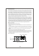
1.Notes on operation:
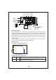
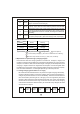
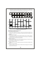
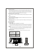
2.Front and back panel
PB-1000 is MW's next generation smart charger. It has many of the protective features
that consu mer s wo u ld like to have in a cha rg er i ncludin g ba tte r y misco nne ction
(wrong voltage), reverse polarity, battery disconnection or not connected, and battery
fai lure analysis. The latest high efficien cy switching topolog y plus microc ontrolle r
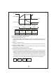
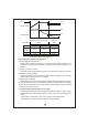
power managemen t ar e utilize d in its desig n. Three types of cha rgin g curve s are
offered for lead acid battery charging, 2 stages for quick charging, 3 stages (quick +
float), and 8 stages for optim ize d charging. Charging stage selection can be easily
made by th e user through the selection switch on the front panel.
Depending on battery brand and type (lead acid, gel, lithium iron, and lithium manganese);
th e battery may require spe cial chargin g curves and adjustm ent t o the protective
functions which differs from the standard settings. The charging curves and protective
functions can be customized by reprogramming its firmware. Basically, you can change
the voltage/current settings of each individual stage plus adjust or cancel the protective
functions. Please note, the factory charging curve is for charging lead-acid battery.
Please contact MW regarding other types of battery charging requirements.
◎Designed for cha rging lead acid batte ry.
◎Must be installed in a dry and well ventilated area. It should not be exposed to rain
or snow.
prevent excessive voltage drop. Too much voltage drop will lead to longer charging
period.
resulting from improp er o per ation wil l result in cancel latio n of warrant y.
◎The cables between charger and bat tery shou ld be kept as sh ort as possi bl e to
◎Please make sure ch arging voltage and c urre nt meets ba ttery specific atio n.
◎Refr ain from connecting new and old batt eries in seri es.
◎Thre e ye a rs war rant y is prov i de d un der norm al o per a tin g con dit io ns. Fa ilur e
◎Charger should be in t he O FF mode befo re ma king battery connection or dis con nec tion.
AC INLET
F an
Venti lation
H ole
Figure 2.1 Front Panel
ON/ OFF SWITCH
ON
AC INPUT
OFF