
Datasheet


For product updates and/or changes of specifications please see www.mec.dk
42
multimec®
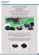
technical information
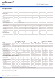
spacing
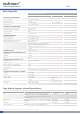
Cap series Recommended
min. switch spacing AxB
Nominal cap dimension
WxH
Recommended
min. panel cut-out
1A/1H 12.7x10.16 12.6x10.1 13.0x10.5
1B/1C+2C/2D 15.24x15.24 15.1x15.1 15.5x15.5
1DS/1ES/1FS 12.7x12.7 ø9.6 ø10.0
1GAS 12.7x11.14 ø11 ø11.4
1GCS 15.14x15.14 ø15 ø15.4
1JS 12.7x12.7 ø9.6 ø10.4
1KS/1KBS/1KCS 15.24x15.24 14.3x14.3 14.7x14.7
1M 25.4x10.16 25.0x10. 25.7x10.5
1NS 12.7x12.7 ø9.8/☐4.9 ø10.2/☐5.1
1PS/1QS/1RS 15.24x10.16 6.5x12.5 7.0x13.0, R max. 1.0
1SS/1IS/1LS 12.7x12.7 ø6.5 ø7.0
1TS 12.7x12.7 10.6x10.6 11.0x11.0
1US 12.7x12.7 ø10.6 ø11.0
1VS 12.7x12.7 10.6x13.25 11.0x13.65
1WAS/1WPS 12.7x10.3 12.5x6.5 12.9x6.9
1WDS 15.34x10.3 15.2x8.0 15.6x8.4
1XS 12.7x12.7 9.4x7.4 9.8x7.9
1YS 17x17 15x15 16x16
1ZA 18.84x10.3 18.7x10.1 19.4x10.5
1ZB 24.34x12.1
R1=7.4; R2=17.5 90° R1=7.1; R2=17.5-17.75 90°
1ZCS 14.44x14.44 ø14.3 ø14.7
1Z/1ZW 35.5x35.5; 41.6x41.6 ø29.5 ø30.3
10R/10RF/10RM 40.5x40.5 ø30.0 ø30.6
10Q/10QM 32.5x32.5 22x22 22.5x2.5
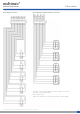
Basic switch spacing
through-hole surface-mount
Recommended switch/cap spacing
Switch spacing Cap dimension
Panel cut-out
Panel Cut-out
1N 1V 1T
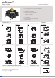
Spacing examples
multimec
®
3AT + 1B/C + 2A/B
multimec
®
3AS + 1B +2A/B
4AS +1B/1C + 2C/2D
multimec
®
3AT + 1A/H
multimec
®
3AT + 1M
multimec
®
1N + 1N + 1N
multimec
®
1V + 1T + 1V
For updates of products and/or changes of speci cations please see www.mec.dk
*A dimension with surface mount version is min. 15.24. Depending on manufacturing technology it may be necessary either to reduce pad dimension, or to increase
spacing.
In all applications the total assembly tolerance must be analysed by the user (board tolerance, front panel, assembly accuracy), to secure enough room for a free switch
movement in the nal product. The speci cations on this page are to be considered as an aid only. MEC cannot be held responsible for the nal assembly.
Cap series Recommended* Nominal cap dimension Recommended
min. switch spacing AxB W x H min. panel cut-out
1A 12.7 x 10.16 12.6 x 10.1 13.0 x 10.5
1B/1C+2A/2B 15.24 x 15.24 15.1 x 15.1 15.5 x 15.5
1D/1E/1F 12.7 x 12.7 ø9.6 ø10.0
1K 15.24 x 15.24 14.3 x 14.3 14.7 x 14.7
1M 25.4 x 10.16 25.0 x 10.1 25.7 x 10.5
1N 12.7 x 12.7 ø9.8/
4.9 ø10.2/ 5.1
1P/1Q/1R 15.24 x 10.16 6.5 x 12.5 7.0 x 13.0, R Max. 1.0
1S 12.7 x 10.16 ø6.5 ø7.0
1T 12.7 x 12.7 10.6 x 10.6 11.0 x 11.0
1U 12.7 x 12.7 ø10.6 ø11.0
1V (pointing outwards) 12.7 x 12.7 10.6 x 13.25 11.0 x 13.65
1X 12.7 x 12.7 9.4 x 7.4 9.8 x 7.9
multimec
®
spacing
Spacing in mm
Center of switch
mec
|
www.mec.dk
34
Basic switch spacing
through-hole surface-mount
Recommended switch/cap spacing
Switch spacing Cap dimension
Panel cut-out
Panel Cut-out
1N 1V 1T
Spacing examples
multimec
®
3AT + 1B/C + 2A/B
multimec
®
3AS + 1B +2A/B
4AS +1B/1C + 2C/2D
multimec
®
3AT + 1A/H
multimec
®
3AT + 1M
multimec
®
1N + 1N + 1N
multimec
®
1V + 1T + 1V
For updates of products and/or changes of speci cations please see www.mec.dk
*A dimension with surface mount version is min. 15.24. Depending on manufacturing technology it may be necessary either to reduce pad dimension, or to increase
spacing.
In all applications the total assembly tolerance must be analysed by the user (board tolerance, front panel, assembly accuracy), to secure enough room for a free switch
movement in the nal product. The speci cations on this page are to be considered as an aid only. MEC cannot be held responsible for the nal assembly.
Cap series Recommended* Nominal cap dimension Recommended
min. switch spacing AxB W x H min. panel cut-out
1A 12.7 x 10.16 12.6 x 10.1 13.0 x 10.5
1B/1C+2A/2B 15.24 x 15.24 15.1 x 15.1 15.5 x 15.5
1D/1E/1F 12.7 x 12.7 ø9.6 ø10.0
1K 15.24 x 15.24 14.3 x 14.3 14.7 x 14.7
1M 25.4 x 10.16 25.0 x 10.1 25.7 x 10.5
1N 12.7 x 12.7 ø9.8/
4.9 ø10.2/ 5.1
1P/1Q/1R 15.24 x 10.16 6.5 x 12.5 7.0 x 13.0, R Max. 1.0
1S 12.7 x 10.16 ø6.5 ø7.0
1T 12.7 x 12.7 10.6 x 10.6 11.0 x 11.0
1U 12.7 x 12.7 ø10.6 ø11.0
1V (pointing outwards) 12.7 x 12.7 10.6 x 13.25 11.0 x 13.65
1X 12.7 x 12.7 9.4 x 7.4 9.8 x 7.9
multimec
®
spacing
Spacing in mm
Center of switch
mec
|
www.mec.dk
34
12,7Min.
10,3
Min.
15,24Min.
10,3
Min.
12,7Min.
10,3
Min.
15,24Min.
10,3
Min.
12,7Min.
10,3
Min.
15,24Min.
10,3
Min.
12,7Min.
10,3
Min.
15,24Min.
10,3
Min.
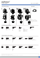
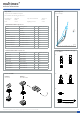
Basic switch spacing
multimec
5GT+1B/C+2C/D
Cap dimensions
Panel cut-out
Panel cut-out
1NS 1VS 1TS
multimec
1VS + 1TS+ 1VS
multimec
1NS + 1NS + 1NS
multimec
5GT + 1A/H
multimec
5GT + 1M
multimec
5GS+1B/C+2C/D
surface mount (SMD)through-hole (TH)
Recommended switch/cap spacing
Switch spacing
Spacing examples