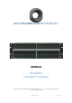
MEDIATECHNOLOGYSYSTEMS INC. MANUAL STAGE8.8 CobraNet™ Interface 766 LAKEFIELD ROAD, WESTLAKE VILLAGE, CALIFORNIA 91361 U.S.A. www.mediatechnologysystems.
FCC Compliance Notice & Interference Statement. THIS DEVICE COMPLIES WITH PART 15 OF THE FCC RULES. OPERATION IS SUBJECT TO THE FOLLOWING CONDITIONS. THIS DEVICE MAY CAUSE HARMFUL INTERFERENCE. THIS DEVICE IS DESIGNED TO ACCCEPT AND OPERATE WITH ANY INTERFERENCE RECEIVED. THIS INCLUDES INTERFERENCE THAT MIGHT CAUSE UNDESIRED OPERATION. CAUTION: ANY CHANGES OR MODIFICATIONS MADE WITHOUT THE EXPRESS APPROVAL AND PERMISSION OF MANUFACTURER, VOID RESPONSIBILITY OF MANUFACTURER FOR COMPLAINCE.
Explanation of Symbols TO PREVENT ELECTRIC SHOCK DO NOT REMOVE COVER. NO USER SERVICABLE PARTS INSIDE. REFER TO QUALIFIED AND CERTIFIED SERVICE PERSONNEL. CAUTION RISK OF ELECTRIC SHOCK DO NOT OPEN The exclamation mark in a triangle is intended to alert the use to the user to the presence of important operating and maintenance/service instructions in this manual.
Table of Contents 1 1.1 1.2 1.3 WELCOME 5 IMPORTANT SAFETY INSTRUCTIONS DECLARATION OF CONFORMITY: HOW TO USE THIS MANUAL. 5 5 5 2 SPECIFICATIONS 6 3 FUNCTIONAL DESCRIPTION 7 3.1 3.2 3.3 3.4 3.5 3.6 3.7 4 4.1 4.2 4.3 4.4 4.
1 Welcome 1.1 Important Safety Instructions Important Safety Instructions: Read these instructions. Keep these instructions. Heed all warnings. Follow all instructions. Do not use this apparatus near water. Clean only with dry cloth. Do not block any ventilation openings. Install in accordance with the manufacturer's instructions. Do not install near any heat sources such as radiators, heat registers, stoves, or other apparatus (including amplifiers) that produce heat.
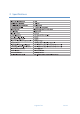
2 Specifications Page 6 of 22 Oct‐12
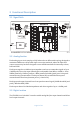
3 Functional Description 3.1 Signal Path + - G + - G 3.2 Analog Section Each analog input circuit employs a fully balanced true differential topology designed to maximize CMRR across all possible input connection methods, where the input and output connectivity has been designed to meet AES48 standards for immunity to hum, buzz and SCIN.
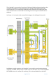
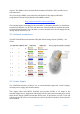
The CobraNet™ port uses the Cirrus Logic CS181xxx/CS496xxx chipset (similar to the commonly used CM2 card). This allows for up to 8 audio input channels from the network and up to 16 audio output channels to the network, 8 local analog mic/line input channels to the network and 8 local analog line level output channels from the network. See Figure 3-1 for details of the internal block diagram for the Digital Section I/O. Figure 3-1: Block diagram showing the Cobranet routing of the STAGE8.
website. The SNMP controls include all the standard CobraNet™ OID’s and the Cirrus DSP extensions. See Cirrus Logic’s UM23 users manual for full details of the chipset and PM25 programmers manual for full details of the SNMP controls… http://www.CobraNet™.info/en/products The 8 analog inputs are mapped to the CobraNet™ transmitter channels 1 to 8 and then repeated on channels 9 to 16. This will allow two unicast bundles to transmit the audio to two different locations.
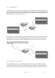
3.6 Connections For standalone crossover connection between two STAGE8.8’s (ie no Ethernet switch), use the two Data in connections to separate the DC supplies. For a typical stage box, the two injectors would be at the control room/mixing console and just the long cable with Data and power to the stage. See below… The Cobranet network port also carries the 24 volt power on the unused 4 wires of the 100BaseTx connection. The STAGE8.8 ships with a 24volt PSU and PoE injector (note the Stage8.
The STAGE8.8 ships with a wall/floor mount accessory (see below) that attaches to the main STAGE8.8 chassis and provides a decorative cover.
4 Simple Configuration (No DSP) The STAGE8.8 ships with the 8 analog inputs linked to CobraNet® Transmitter sub channels 1‐8 and CobraNet® Receiver sub channels 33‐40 are linked to the 8 analog outputs. This allows the STAGE8.8 to be used ‘out of the box’ by merely setting up Transmitter and Receiver (‘Bundle’) network addresses. However, the STAGE8.
• • Finally, change the selection from “Obtain an IP address automatically” to “Use the following IP address” and set to your desired IP domain, eg:‐ • IP address: 192.168.192.50 • Subnet mask: 255.255.255.0 After finishing using the CNDISCO application, return to the Control Panel and reset the selection back to “Obtain an IP address automatically”. If an intelligent or managed switch/router is in use, then the switch address will need to be set to the same subnet, usually 192.168.1.1 or 192.168.1.
Save the changed .ini/config file and exit Notepad. The advanced features are now enabled. Now when you update the firmware you'll see a check box in the "Select Firmware Version" dialog box marked "Show All Firmware Versions". Check the box and you'll be able to choose from all the firmware versions stored in the firmware directory. 4.
Multicast over 1 – If more than one receiver is set to receive this bundle, it will be multicast, else it will be Unicast Multicast over 2 – If more than two receivers are set to receive this bundle, then it will be multicast, else it will be unicast or multi‐unicast Multicast over 3 – If more than three receivers are set to receive this bundle, then it will be multicast, else it will be unicast or multi‐unicast Multicast over 4 – If more than four receivers are set to receive this bundle, then i
o Bundle number: Same process and limitations as described in the transmitter section o Receiver active: This LED only lights if there is a valid transmitter sending audio on that bundle address and channel.
simple local network with a single Ethernet switch, then 1.33mS can be safely used. If more than 1 switch, then use 2.67mS. If more than 3 switches, then use 5.33mS. o The “Location” is a useful way of uniquely naming the STAGE8.8 interface. Up to 60 characters, eg “Ballroom 3: Stage left, Mics 7/8”. For more detailed naming information in a large project, both the “Location” and “Contact” fields can be used. Figure 4-4: Global Interface settings 4.4 Presets The STAGE 8.
1 minute to save, as they are stored in between other processes. Also note that DSP settings are not stored‐only Cobranet interface settings. 4.5 Setting a static IP address First set persistence on (see Section 5). Then double click on the device in the main CNDISCO window to open the configuration menu (see below). In the configuration menu select the “SNMP” button. An SNMP window will open and select the “Monitor” Group and the “ipMonStaticIP” variable.
5 Firmware The Cobranet firmware is updated using the free utility (Cobranet Discovery) from Cirrus Logic – see Figure 5-1 below. Figure 5-1: Cobranet Discovery showing 2.11.9 firmware After loading the CNDISCO application, Advanced features will need to be enabled. Enabling advanced features in CNDISCO allows you to put any version of firmware on any hardware‐compatible Cobranet module you wish.
First Click on Cobranet and then choose Upload firmare… Now when you update the firmware you'll see a check box in the "Select Firmware Version" dialog box marked "Show All Firmware Versions". Check the box and you'll be able to choose from all the firmware versions stored in the firmware directory. Then choose all “Unconditionally” and select the “MTS_2_11_xx.bin”… binary and hit Update. You will get a warning, so accept and then see the updating dialog box below. Once completed, power cycle the product.
Page 21 of 22 Oct‐12
6 INDEX A Advanced Feature=1, 13 B Bundle number, 14, 16 P Persistance, 16 persistence, 16, 17 PM25, 16 Power Supply, 9 Presets, 17 R C CC_Enable=1, 13 CNDISCO, 12, 13, 14, 16 Cobranet firmware update, 19 Cobranet flash, 17 CobraNet™ Discovery, 13, 14 Contact, 17 CS496112, 14, 15 L Receiver active, 16 Receiver setup, 15 S Safety, 5 Signal Path, 7 Specifications, 6 Subformat Resolution, 14 T LED, 7 Location, 17 Transmitter setup, 14 M Max Unicast, 14 Mode Rate Control, 16 U Unicast mode, 14 Unicas