iCAMView User Manual Version 2.2 For models: iCV-01a / iCV-01b / iCV-02 / iCV-03 Copyright Information Copyright © 2004, Mega System Technologies, Inc. All rights reserved. Reproduction without permission is prohibited. Technical Support and Contact Information Mega System Technologies, Inc. Tel: +886-2-87922060 Fax: +886-2-87922066 Web: www.megatec.com.tw iCAMView Web: www.icamview.com Customer Service: service@megatec.com.
CONTENTS Chapter 1: Introduction ________________________________________1 Section 1. Features ___________________________________________1 Section 2. iCAMView as a Remote Surveillance System ______________1 Section 3. Package Contents ___________________________________2 Chapter 2: Installation Procedure ________________________________4 Chapter 3: iCAMView, USB Camera and the Network ________________5 Section 1.
2.4.4 E-mail / FTP ___________________________________________39 2.4.5 System Settings ________________________________________42 2.4.6 Image Server __________________________________________45 2.4.7 Language _____________________________________________46 2.4.8 About ________________________________________________47 2.5 Viewing images using PDA / Web enabled mobile phone __________48 Chapter 6: iMultiView _________________________________________50 Section 1.
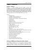
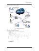
Chapter 1: Introduction Chapter 1: Introduction Section 1. Features iCAMView is a compact stand-alone web-server capable of remote video surveillance. It can be accessed from anywhere in the world via a standard browser by entering the IP, account and password. Each system can simultaneously support any two combinations of USB PC cameras be it regular, infrared or pan-tilt. With its built-in web-server, iCAMView can stream video images directly to the Internet without have to go through a computer.
Chapter 1: Introduction monitor his factory production in China, and if he likes, check on his branch office located in Singapore, all simultaneously. Fig.1. iCAMView Network Diagram Section 3. Package Contents Your iCAMView package should contain the following items; 1. iCAMView, 2. Quick Installation Guide 3. iCAMView Utility CD, which contains; a. iCAMView Utility: to configure IP address, update the firmware, etc. b. iMultiView: Windows platform to monitor multiple iCAMView. c.
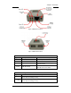
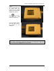
Chapter 1: Introduction Fig.2. iCAMView Front View Fig.3. iCAMView Back View LED Status Indicators on iCAMView Light color Green Signal definition Condition description Power state On: Normal power Error Condition On: Error condition occurred Orange Logon state On: When there is user logon and receive the image. Yellow USB data activity Flash when there is transmit/receive on the USB. Red data Fig.4.
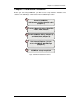
Chapter 2: Installation Procedure Chapter 2: Installation Procedure Before you start using iCAMView, you will need to set-up both the hardware and software. The following is a flow chart on the installation procedure: 1 2 Connect iCAMView, USB Camera and the Network cable (Chapter 3) Connect Network cable to ROUTER / HUB / xDSL modem 3 Install iCAMView Utility (Chapter 4) and iMultiView (Chapter 6) 4 Use Internet Explorer (>5.0) to access iCAMView Web Manager (Chapter 5).
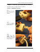
Chapter 3: iCAMView, USB Camera and the Network Chapter 3: iCAMView, USB Camera and the Network The following details the installation procedure for iCAMView. Section 1. Installation Procedure Step 1: Connect the PC camera into the USB port of iCAMView. Step 2: Connect the iCAMView to LAN by using the Ethernet UTP port.
Chapter 3: iCAMView, USB Camera and the Network Step 4: The LCD will display the IP, Subnet Mask and Gateway IP. Use a WEB browser to login into the iCAMView IP address. The icon on the LCD shows that a USB camera is connected. The LCD display shows that two USB cameras are attached to the iCAMView. Warning: Please make sure the input Voltage and Frequency of the DC power adapter (DC 5.
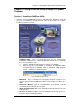
Chapter 4: Using iCAMView Utility to Setup IP & Update Firmware Chapter 4: Using iCAMView Utility to Setup IP & Update Firmware Section 1. Installing iCAMView Utility 1. Insert the enclosed iCAMView CD into the CD-ROM drive. iCAMView setup will auto run. The following menu will show up. Click on the buttons on the left to install the programs you want. " iCAMView Utility - This is a program that helps the user perform quick installation.
Chapter 4: Using iCAMView Utility to Setup IP & Update Firmware Section 2. Using iCAMView Utility The iCAMView Utility main menu is shown below. The selection menu is located on the left. The Serial Number, current Firmware and IP Address of every iCAMView connected to the LAN will be displayed on the table to the right. Fig.8.
Chapter 4: Using iCAMView Utility to Setup IP & Update Firmware 2.1 Setup Wizard Use “Setup Wizard” to take you through the basic configurations necessary to start using iCAMView. 1. Click to highlight the iCAMView on the right that you want to configure. 2. Click on “Setup Wizard”. 3. iCAMView Setup Wizard will initiate to take you through the installation. 4. Enter the necessary camera configurations.
Chapter 4: Using iCAMView Utility to Setup IP & Update Firmware Enter an appropriate internal IP Address, Subnet Mask and Gateway for iCAMView (Refer to Appendix C for an explanation of IP Addresses) “Obtain an IP address by Bootp” Allow iCAMView to obtain an IP address using Bootp protocol. 6. Click “Next >” to proceed to xDSL/Cable modem setup. This section has to be configured to allow iCAMView to access the Internet through an xDSL.
Chapter 4: Using iCAMView Utility to Setup IP & Update Firmware 7. Click “Next >” to proceed with DDNS setup or registration You will need to setup this section if you are using a Dynamic IP If you do not already have a Domain Name registered with your ISP, select from one of the 4 Free DDNS service providers (3322.org, dhs.org, dyndns.org or myddns.org). Follow the link to the respective free service providers to register a Domain Name and obtain a User Name and Password.
Chapter 4: Using iCAMView Utility to Setup IP & Update Firmware 8. Click “Next >” to create an administrator account and password. An administrator account is necessary to ensure privacy. iCAMView can be viewed by anyone on the web. If you do not set one, WARNING: Do not lose the administrator account and password. Once set, you will not be able to configure iCAMView without the administrator account and password. 9. Click “Next >” to upload these configuration to iCAMView.
Chapter 4: Using iCAMView Utility to Setup IP & Update Firmware 10. Click “Next >” to save and restart iCAMView with the new configurations. 2.2 Launch iCAMView Once you have finished with the above Setup Wizard, either click “Launch iCAMView” or double click on the iCAMView listed on the table to launch it. Click either one to Launch iCAMView. Once you have done the above, the iCAMView login screen will appear.
Chapter 4: Using iCAMView Utility to Setup IP & Update Firmware The iCAMView webpage will appear. images. Click ActiveX for Camera A to view the video 2.3 IP Configuration This section allows you to determine IP address configuration for iCAMView. Select the iCAMView on the right display screen, and then click “IP Configuration”. This will bring up the IP Address Configuration window. There are two tabs; • IP Address • Advanced (for port setting configuration) 2.3.
Chapter 4: Using iCAMView Utility to Setup IP & Update Firmware Use this section to set the IP Address of iCAMView. When using iCAMView for the first time, it is advisable to choose the “Using Static IP Address” option. For this option, the user will have to enter an IP Address, Subnet Mask and Gateway of their choice (refer to Appendix C for IP address explanation). Fig.9.
Chapter 4: Using iCAMView Utility to Setup IP & Update Firmware Fig.10. IP Configuration: iCAMView Advanced settings i. Device Password Use this to set an access password to the individual device. Once set, the user must enter the password to access the device. In addition, the IP Address will not be shown on the right display panel of iCAMView Utility. Devise Password enabled. IP Address hidden. Devise Password not set.
Chapter 4: Using iCAMView Utility to Setup IP & Update Firmware WARNING: Do not lose this password. If the password is lost, you can not access the device to make changes. To remove the password, you must first enter a valid “Input Device Password”, go to “Device Password” and delete the entries, click “OK”. ii. Management Protocol The administrator can determine the parameter settings when providing access via HTTP (web) to iCAMView.
Chapter 4: Using iCAMView Utility to Setup IP & Update Firmware Fig.11. Upgrade Firmware: Updates iCAMView firmware If you have downloaded the latest firmware to your local hard drive, check “Upgrade the iCAMView firmware with file saved on the local hard drive” and browse to the file location. 2. Click “Next >” to check for the latest available firmware. 3. Select new firmware file (*.bin) and, 4. Click “Start”.
Chapter 4: Using iCAMView Utility to Setup IP & Update Firmware 2.5 About Click on this button to show software and version details. Fig.12. About iCAMView Utility 2.6 Refresh iCAMView Utility automatically searches for any iCAMView connected to the LAN. However, the user can do a manual search by clicking the “Refresh” icon located at the bottom right of the menu.
Chapter 5: iCAMView Web Manager Chapter 5: iCAMView Web Manager Section 1. Introduction After you have setup the hardware and set an IP address for iCAMView, you will then be able to go to iCAMView web site to monitor and control the PC cameras. All you have to do is enter the new IP address into any web browser. 1. Start the Web Brower (Netscape or Internet Explore) 2. Enter the iCAMView IP Address that was set earlier using “Setup Wizard” (e.g. 192.168.0.
Chapter 5: iCAMView Web Manager 2.2 Information 2.3 Basic Settings 2.4 Advanced Settings 2.5 Viewing images using a PDA / Web Enabled Phone Fig.15. iCAMView Main Menu When using iCAMView for the first time, you must set the following to ensure that iCAMView works smoothly; a. b. Set the necessary parameters in the “Configuration” menu. In particular, the “Anti Flicker” under “Camera Settings” should be set to 50Hz or 60Hz (change this to 60Hz or 50Hz / Outdoor if video output continues to flicker).
Chapter 5: iCAMView Web Manager 2.1 Web-Camera Selection Click on either “ActiveX” or “Sun Java” from Camera A or B to view the camera images. By default the first USB camera connected to iCAMView will be denote as “Camera A” Click “Camera B” to view camera B. Note: ActiveX can only function on Windows platform and a plug-in has to be installed on the client's computer. If this is prohibited for safety reasons you will have to use Sun Java to view the video feed.
Chapter 5: iCAMView Web Manager To change Video Codec, click Note: The availability of Codec depends on weather the individual user has it installed on the PC or not. Download and install Windows Media Player 10 to enable MPEG4 codec. Digital Zoom In, Digital Zoom Out Rotate Left, Rotate Right Flip the image vertically. Auto Pan the camera Pan Left by 5 deg / Pan Left by 1 deg. Pan Right by 1 deg / Pan Right by 5 deg. Tilt Up by 5 deg / Tilt Up by 1 deg. Tilt Down by 1 deg / Tilt Down by 5 deg. 2.
Chapter 5: iCAMView Web Manager Fig.16. iCAMView System Status ii. System Information This section shows iCAMView Network settings. The MAC Address is unique to every iCAMView. All the other values are set by the user in Setup Wizard. 2.2.2 Current Connections This section will show all the users currently viewing either Camera A or Camera B. It also lists, the login time, and total bytes received.
Chapter 5: iCAMView Web Manager Fig.17. iCAMView Current Connections 2.2.3 Event Log This section will keep a record of all events that occurred in iCAMView. The user can Refresh, Clear or Save the log file. There is also an option to sort the logs according to “Level” or “Type” iCAMView can log up to 2,000 events Note: If you do not have Administrator privilege, the User Name and IP will be hidden. "Camera A: user ******** connected from IP: *.*.*.*" Fig.18. iCAMView Event Log 2.
Chapter 5: iCAMView Web Manager Fig.19. Individual Camera Configuration “Anti Flicker” Choose between 50Hz, 60Hz or Outdoors. Note: If you do not choose the right frequency, the image will flicker or lines will appear on the images. “Maximum Number of Connections (1-30)” Use this to limit the number of users that can connect to this camera. “Location” Enter a suitable location / name for the camera. “Light Compensation” Choose “Yes” and iCAMView will increase the lighting of the image.
Chapter 5: iCAMView Web Manager This option determines the iCAMView Network settings. i. IP Address These items were all setup earlier in Setup Wizard. click “Apply” to change. Enter new addresses and Fig.20. iCAMView IP Address Settings “IP Address” This item determines iCAMView IP Address. “Subnet Mask” This item sets iCAMView Subnet Mask. The value is normally 255.255.255.0 “Gateway” This item is to set iCAMView Gateway.
Chapter 5: iCAMView Web Manager “Communication to Camera Port Number” By default the port number is 9001. iv. Ethernet Fig.23. iCAMView Ethernet Settings “Connection Type” This item sets the communication speed between iCAMView and the Network. iCAMView will reboot after “Connection Type” is changed. v. Dynamic DNS Fig.24. iCAMView Dynamic DNS Settings “Service Provider” The iCAMView can be configured to register the current IP to a dynamic DNS provider.
Chapter 5: iCAMView Web Manager Choose “Yes” or “No”. iCAMView will automatically send the WAN IP to the DDNS server. This ensures that DDNS is notified of your current Dynamic IP. vi. PPPoE Use this option to allow iCAMView to directly dial-up using your xDSL modem and connect to the Internet. Once set-up, iCAMView will be able to stream the video images directly to the Internet without going through a router. Fig.25.
Chapter 5: iCAMView Web Manager Operator: Viewer: No Access: This permission level allows the user access to iCAMView menus, but without the permission to amend them. This permission level allows the user to access iCAMView at specific time as set in “Permit Hours” for seeing camera. The user does not have write permission and can only access the “Camera” and “Information” section. This is to revoke either of the above two permission levels given to a user. This disables the user account.
Chapter 5: iCAMView Web Manager Fig.27. iCAMView Permit Hours Configuration 2.4 Advanced Settings Please ensure that each of the following option is set correctly. Otherwise, iCAMView may not work properly. 2.4.1 Event Notification 2.4.2 Motion Detection 2.4.3 Image Recording 2.4.4 Email / FTP 2.4.5 System Settings 2.4.6 Language 2.4.7 About 2.4.1 Event Notification This section determines the type of event an email is sent by iCAMView. iCAMView can send notifications to up to 8 email recipients.
Chapter 5: iCAMView Web Manager Fig.28. iCAMView Event Notification Page i. Event Notification “Send Email” To activate Event Notification, you will need to set “Send Email” to “Yes”. Select “No” if you do not wish to send out any notification. “Email Server” A valid “Email Server” with username and password (if authentication is required) must be made available for this feature to work. If you do not have this setup, or wish to change the settings, click on “Edit”.
Chapter 5: iCAMView Web Manager Fig.29. iCAMView Event Selection List By default, all the events are selected; you must click “Apply” to activate them. Close the window to return to the Event Notification Page. Click “Apply” to save your settings. iCAMView will send you the following email notification depending on which event you have selected. Note: The image recording and motion detection notification function here will send an email notification WITHOUT any pictures attached.
Chapter 5: iCAMView Web Manager Fig.30. iCAMView Event : Start Up Fig.31. iCAMView Event : User Login Details (Date, Time, Camera & IP) Fig.32.
Chapter 5: iCAMView Web Manager Fig.33. iCAMView Event : Camera A or B Motion Detected 2.4.2 Motion Detection This page allows the administrator to set motion detection functions for the cameras. i. Camera A (or Camera B) “Enable” To activate motion detect, the administrator has two options; a. “Always On” or b. “On Schedule”, the administrator can set up to 4 different time slots for motion detection. “Detection Sensitivity” This will determines level of change before motion capture is triggered.
Chapter 5: iCAMView Web Manager Fig.34. iCAMView Motion Detection Page “Send to FTP Server” This option allows the administrator to send and store the motion detected images on a FTP site. This is useful for future reference and recording purpose. Click “Yes” to activate. “ftp:///” This box allows the administrator to determine the file location within the FTP site. If you have not entered a FTP server, the above will be left .
Chapter 5: iCAMView Web Manager “Loop from ## to ##” This will determine the number of suffixes preceding the above filename. Once the last number is reached, the first file will be replaced by the most current image. “Digits” This will determine the number of digits assignable for the above number suffix. The administrator can choose to assign between 1 to 6 digits. Click for an example. “Send Email” To send an email notification of Motion Detection with image, choose “Yes”, otherwise choose “No” Fig.
Chapter 5: iCAMView Web Manager . click Click To add all the email address at once, click , or . To remove an entry to remove all entries from the recipient list. to confirm and save the above settings. 2.4.3 Image Recording Image recording allows the user to receive an image to either their email account or to a FTP server. The images will be sent over a predetermined interval and a certain period. Fig.36. iCAMView Image Recording Page i.
Chapter 5: iCAMView Web Manager This is similar to the function available in Motion Detection Page. Please refer to section 2.4.2 for details. Fig.37. iCAMView Email of Image Recorded 2.4.4 E-mail / FTP This section sets up the necessary Email and FTP server information. The administrator will have to enter a valid Account Name and Password to the Email server and/or FTP server. This information is necessary to allow email notification and ftp file sending features in Advanced Settings.
Chapter 5: iCAMView Web Manager Fig.38. iCAMView Email / FTP Page i. FTP Settings “FTP Server” The administrator will have to enter the FTP server address here. “Account Name” Enter the FTP account name here. “Password” Enter the corresponding password. Click “Apply” to save the above settings. ii. Email Settings “E-mail Server” The administrator will have to enter the Email server address here. “Sender’s Email Address” This will determines iCAMView’s Email address.
Chapter 5: iCAMView Web Manager “Account Name” Enter the account name or login name to the Email server. “Password” Enter the password for the above account name. Click “Apply” to save the above changes. iii. Sending Test Mail Fig.39. iCAMView test mail function You must have the “Email Setting” section configured to proceed with “Test Mail”. Once that is done click “Test Mail” and the following will appear. Click “Yes” to confirm sending and the following window will appear.
Chapter 5: iCAMView Web Manager iv. Email Address Book Fig.40. iCAMView E-mail Address Book Entry Enter an Email address in the box provided and click “Add Email Address”. The new email address will be added to the list. The administrator can store up to 20 email addresses here. To delete an Email address, just press “Delete”. 2.4.5 System Settings This page allows the administrator to set iCAMView SNMP settings so it can be used by a NMS (Network Management System) like iMultiView.
Chapter 5: iCAMView Web Manager i. System Time Fig.41. System Time “Time Between Automatic Updates” The administrator can set an interval for time synchronization. Select either 1, 3, 12 hours or 1, 10 & 30 days. “Time Server” Choose the nearest Time Server to your iCAMView location. can choose from the list of a maximum of 30 Time Servers. The administrator To add a new Timer Server the administrator must first make space by deleting some Time Servers.
Chapter 5: iCAMView Web Manager This section is to manually set iCAMView System Time. The format is pre-determined to: yyyy/mm/dd hh:mm:ss. Click “Manual Adjust” to save any manual changes. ii. System Restart Fig.42. Auto Restart setting “Auto Restart System Every” The administrator can choose to restart iCAMView at certain intervals (choose between minutes and hours only). This will ensure that iCAMView will work smoothly. Click “Apply” to save changes.
Chapter 5: iCAMView Web Manager “Manager IP Address” This set the IP address where the administrator can manage iCAMView from. It is valid for up to 8 IP addresses. To manage iCAMView from any IP addresses leave it as *.*.*.*. “Community” This is to set a Community name for NMS. The community name has to be the same as that set in NMS. “Permission” This is to set the administrator’s authority. Options are Read, Read/Write, and No Access. “Description” This is for an administrator to make notes. 2.4.
Chapter 5: iCAMView Web Manager This is the default port for image stream. User can change this UDP Port to their desired or designated port number. If you intend to change, it must be done prior to logging onto the Image Server. “Login Name” Enter your login name for your image server account. You only have to configure this once. “Login Password” Enter your password. You only have to configure this once. Click “Apply” to confirm all changes. 2.4.
Chapter 5: iCAMView Web Manager 2.4.8 About The administrator can use this section to check firmware information, save/restore settings, upgrade firmware and see manufacturer’s details. i. About This section gives crucial information about iCAMView’s Firmware Version, Hardware Version and Serial Number. These are required information for service calls. ii. Save / Restore Settings “Save current Configuration” Click “Save” to save the current settings and configuration to your PC.
Chapter 5: iCAMView Web Manager Click to check for the latest firmware. and install the latest firmware iCAMView will automatically download Fig.44. iCAMView checking for latest firmware to upgrade 2.5 Viewing images using PDA / Web enabled mobile phone You can view images from your PDA or mobile phone if it has GRPS and a web browser. Type http://xxx.xxx.xxx.xxx/image.cgi (where xxx is your IP address or Domain name) Click on either one to display the picture. Fig.45.
Chapter 5: iCAMView Web Manager Fig.46. iCAMView image The images are being displayed one at a time. “Refresh”.
Chapter 6: iMultiView Chapter 6: iMultiView iMultiView is a program to manage multiple iCAMViews in a network. It is able to detect the IP’s of all the iCAMViews installed, and display them in a list form for easy management. Section 1. Installing iMultiView n Click on setup.exe and follow the installation wizard o After installation, there will be a iCAMView group in the Windows Start group p Click “iMultiView” Æ “iMultiView for Windows” to start using iMultiView. Section 2.
Chapter 6: iMultiView 2.1 Device : Start iMultiView and press the “Enumerate” button, iMultiView will start a search for all the iCAMView on the network and list them in the main window. Once detected, the following will show in the main window: This shows that the camera is online and active.
Chapter 6: iMultiView : Manually adds the iCAMView to be monitored. “Access by iCAMView Address” Enter either the WEB, without the www (Example: megateccn.myddns.com) or LAN IP of iCAMView (example: 192.168.0.30) “Remote Port” This is iCAMView UDP port. “Access by Image Server”. Enter the information as set in Section 2.4.6. : Highlight the iCAMView to be deleted from iMultiView’s list. Click “Yes” to confirm deletion of selected iCAMView.
Chapter 6: iMultiView : Use this function to change iCAMView Address & Port Number. Display the current Camera settings. Camera Select: Account: Password: Image Zoom: iCAMView user manual Select either camera A or B If you have setup user account, the information must be entered here. Otherwise access will be denied. Enter the above account password.
Chapter 6: iMultiView 200% Camera Rotation: Use this function to keep the camera up-right. Mirror the Image: To mirror the image. Maximum frame per Select from 0.01 fps to a maximum of 30.00 second: fps. Display the Motion Detection Settings. Enable Motion Detect: Click the checkbox to enable Motion Detection. Note: This feature requires the Camera Window be active to work. Click “Monitor” to activate the Window.
Chapter 6: iMultiView Image Compression: Recording AVI File Path Choose from the list of available compressions. Note: This list is dependent on the Codec that is available or already installed on the local PC. To record in MPEC-4, make sure you install or upgrade to Windows Media Player v10. Location where the file will be recorded to. By default, it is recorded to C:\Program Files\iCAMView\iMultiView. Click “Browse” to change the file location.
Chapter 6: iMultiView change the display view or add a new folder here. Stop after idle for: Set the value between 1 to 100 seconds Send AVI file Notification by Email: Send an AVI file via email in the event any motion is detected. Configure Settings for Email Notification You will need to enter the correct “Message Sender Information” in order for iCAMView to send emails.
Chapter 6: iMultiView SNMP Settings Host Name: Provide a Name to identify this device. HTTP Port: Enter the HTTP port assigned for iCAMView. Location: Provide a location for SNMP manager to track device. Manager: Enter a manager’s name for identification.
Chapter 6: iMultiView Move the curser over the edges of the picture and it will turn into an arrow. Click and hold to pan / tilt the camera (if the camera supports this function) Click this button to record the current image on screen. A window will come up, click “Start” to start recording to the default file and location. Flip the image vertically Rotate Left, Rotate Right Click this to bring up the Setting windows. Click this to switch to full screen view. Double click to switch back to current view.
Chapter 6: iMultiView Click the left side of the viewing window to bring out more control features. Clicking once will cause the camera to pan left by 1 deg. Click and hold and the camera will pan increasingly faster to the left. Clicking once will cause the camera to pan right by 1 deg. Click and hold and the camera will pan increasingly faster to the left. Click once to tilt the camera up by 1 deg. Click and hold and the camera will tilt increasingly faster upwards.
Chapter 6: iMultiView 2.2 View : Switch between Large or Small icon view Large icon display Small icon display 2.3 System : Display the Event Log (IP address, Port, date, Time, description of event) of the selected iCAMView. : Set the SNMP Parameter.
Chapter 6: iMultiView 2.4 User Change Password : “Change Password…” Use this feature to change the current User login password to iMultiView. Both “Administrator” or “User” can change their own Account passwords. “Account Management…” Use this section to Add, Delete or Change the Password of an Account. Click “Add User…” can be added. There is no limit to the number of Account that Note: The first account is set to “Admin” with “Administrator” permission. This cannot be changed or deleted.
Chapter 6: iMultiView Account: Enter the preferred account name (max of 10 characters). The Account name cannot be edited. Password: Enter a password (max of 10 characters). The password is case sensitive and can be left blank. Permission: Choose “Administrator” or “User”. An “Administrator” can change, see, add or delete any of the information in iMultiView. A “User” is not able to Add, Delete or Change Settings of a camera. 2.
Chapter 6: iMultiView Step 3: Release the mouse button anywhere on the desktop and a new desktop icon is created there. Step 4: Double click on the icon on the desktop, to view the images.
Appendix A: Router Configuration Appendix A: Router Configuration The following section describes the initial configuration of the router and port forwarding for your router. If your router is not listed here, please refer to the manufacturer’s website for assistance with configuring your router to work with iCAMView. Port Forwarding for iCAMView iCAMView requires certain ports to be open on your router to allow other computers on the Internet to “see” it on your internal network.
Appendix A: Router Configuration NETGEAR Proxim Siemens SMC MN-500 RP614 MR814 MR314 FVS318 ORiNOCO BG-2000 Broadband Gateway SpeedStream 2602 SpeedStream 2623 SpeedStream 2604 SpeedStream 2624 SMC2404WBR SMC7004VBR SMC7004CWBR SMC7004AWBR iCAMView user manual Wireless Base Station Web Safe Router Wireless Router Cable/DSL Wireless Router ProSafe VPN Firewall 2-Port DSL/Cable Router Wireless DSL/Cable Router 4-port DSL/Cable Router Wireless DSL/Cable Router Barricada Turbo 11/22 Mbps Wireless Cable/DS
Appendix A: Router Configuration 3Com (http://www.3com.com) 3C857-US – OfficeConnect Cable/DSL Gateway 3CRWE52196 – OfficeConnect Wireless Cable/DSL Gateway 1. Log into your router using your router IP. 2. On the main page, select Firewalls on the left side of the page. 3. Select the Virtual Servers tab at the top of the page. 4. Click New on the right side of the page to open the Virtual Server Settings dialog box. 5. Type in the camera’s IP address in the Server IP address text box.
Appendix A: Router Configuration Belkin (http://www.belkin.com) F5D6230-3 – Wireless Cable/DSL Gateway Router 1. Log into your router using your router IP. 2. On the main page, select Virtual Server on the left side of the page under the Securit section. 3. Enter the following information on the page: Line #1: Private IP: Type in the camera’s IP address.
Appendix A: Router Configuration Private Port Line #2 Enable: Description: Internet Port: Type: Private IP address: Private Port 80 to 80 Checked in iCAMView – Camera 9001 to 9001 UDP Type in the camera’s IP address. (Look on the iCAMView Address LCD display for the last 3 digits of the camera’s IP address) 9001 to 9001 5. Click Apply Changes to save the settings. The iCAMView should now be configured o work with your router and be accessible from the internet.
Appendix A: Router Configuration D-Link (http://www.dlink.com) DI-604/DI – 614+/DI-624 1. Log into your router using your router IP. 2. On the main page, click on Advanced at the top of the page. 3. On the left side of the page, click on Virtual Server. Note: Make sure DMZ host is disabled. If DMZ is enabled, it will disable all Virtual Server entries. 4.
Appendix A: Router Configuration Enabled/Disabled: Enabled For ID#2 Service Port: Service IP: Enabled/Disabled: 9001 Type in the camera’s IP address, for example: 192.168.0.5 Enabled 4. Save your settings. iCAMView should now be configured to work with your router and be accessible from the internet. DI714 1. Log into your router using your router IP. 2. On the main page, click on Advanced at the top of the page. 3. Click on Virtual Server Settings on the left side of the page. 4.
Appendix A: Router Configuration Dell (http://www.dell.com) TrueMobile 2300 Wireless Broadband Router 1. Log into your router using your router IP. 2. On the main page, click on Advanced Settings at the top of the page. 3. Go to the Port Forwarding section and select Custom Port Forwarding Settings. 4. Check the Enable box. 5. Enter the desired name or description in the Service Name field such as iCAMView Web. 6. In the Incoming Ports field, specify port 80 in both boxes. 7.
Appendix A: Router Configuration Linksys (http://www.linksys.com) BEFSR41 – EtherFast Cable/DSL Router BEFSX41 – Instant Broadband EtherFast Cable/DSL Firewall Router with 4-Port Switch/VPN EndPoint BEFW11S4 – Wireless Access Point Router with 4-Port Switch – Version 2 1. Log into your router using your router IP. 2. On the router’s main page, click on Advanced at the top of the page. 3. On the next page, click on Forwarding. 4.
Appendix A: Router Configuration Microsoft (http://www.microsoft.com/hardware/broadbandnetworking) MN-100 – Wired Base Station MN-500 – Wireless Base Station 1. Log into your router using your router IP. 2. Open the Bass Station Management Tool, and then click Security. 3. On the Security menu, click Port Forwarding, and then click Set up persistent port forwarding. 4. In the Enable checkbox, check in the checkbox. 5. In the Description box, type a description of the server field such as: iCAMView Web. 6.
Appendix A: Router Configuration NETGEAR (http://www.netgear.com) RP614 – Web Safe Router MR814 – Wireless Router 1. Log into your router using your router IP. 2. Click Advanced -> Port Forwarding on the left side of the page. 3. Click Add Customer Service. 4. Enter the following information on the page: Service Name: iCAMView – Web Starting Port: 80 Ending Port: 80 Server IP Address: Type in the camera’s IP address, for example: 192.168.0.5 5. Click Apply to save the settings. 6.
Appendix A: Router Configuration Line #2: Starting Port: Ending Port: Server IP Address: 9001 9001 Type in the camera’s IP address, for example: 192.168.0.5 5. Click Apply to save the settings. iCAMView should now be configured to work with your router and be accessible from the internet. FVS318 – ProSafe VPN Firewall 1. Log into your router using your router IP. 2. On the main page, click on Add Service on the left side of the screen. 3. Click Add Customer Service. 4.
Appendix A: Router Configuration D. Local Server Address: Enter the IP address of the camera E. WAN Users Address: Any F. Click Apply. 12. Click Add again. A. For Service name select: iCAMView Cam B. Action: ALLOW always C. Local Server Address: Enter the IP address of the camera D. WAN Users Address: Any E. Click Apply. 13. Exit the router setup program. iCAMView should now be configured to work with your router and be accessible from the internet.
Appendix A: Router Configuration Proxim (http://www.proxim.com) ORiNOCO BG-2000 Broadband Gateway 1. Log into your router using your router IP. 2. On the router’s main page, click on Setup at the top of the page. 3. On the left side of the page, click on Advanced settings -> Port Forwarding. 4. Check in the checkbox for Enable Port Forwarding. 5. Click New on the right side of the page. 6.
Appendix A: Router Configuration Siemens (http://www.speedstream.com) SpeedStream 2602 – 2-Port DSL/Cable Router SpeedStream 2623 – Wireless DSL/Cable Router SpeedStream 2624 – Wireless DSL/Cable Router 1. Log into your router using your router IP. 2. After you are logged in, click on Advanced Setup -> Virtual Servers. 3. Enter the following information on the page: Line #1: Private IP: Type in the camera’s IP address, for example: 192.168.0.
Appendix A: Router Configuration 7. Under Internal Port No type in: 80 8. Under External Port No type in: 80 9. Click on Add to save these settings. 10. Under the first box, next to the Enable checkbox, type in: iCAMView Cam. 11. Under PC (Server), select your camera or the camera’s IP address from the list. If the camera is not listed, select the link titled “My PC is not listed.” 12. Leave Protocol as TCP. 13. Under Internal Port No type in: 9001 14. Under External Port No type in: 9001 15.
Appendix A: Router Configuration SMC (http://www.smc.com) SMC2404WBR – Barricada Turbo 11/22 Mbps Wireless Cable/DSL Broadband Router SMC7004VBR – Barricada Cable/DSL Broadband Router SMC7004CWBR – Barricada Wireless Cable/DSL Broadband Router 1. Log into your router using your router IP. 2. After you are logged in, click NAT on the left side of the page. 3. Click on Virtual Server on the left side of the page. 4.
Appendix A: Router Configuration For ID #2: Service Port: Private IP: Enable: 9001 Type in the camera’s IP address, for example: 192.168.0.5 (Look at iCAMView’s IP Address LCD display for the last 3 digits of the camera’s IP address) Checked in 4. Click Save to save the settings. iCAMView should now be configured to work with your router and be accessible from the Internet.
Appendix C: IP Address, Subnet and Gateway Appendix B: Methods to Update iCAMView Firmware You can update iCAMView’s firmware using any of the following methods. Method 1: Using iCAMView Utility (1) Use “Download Firmware” function under iCAMView Utility to update it Method 2: Through iCAMView Web Page (1) Enter the iCAMView Web Page (2) Go to “About”, click “update software” and you will be automatically linked to MegaTec’s website for update.
Appendix C: IP Address, Subnet and Gateway Appendix C: IP Address, Subnet and Gateway This section discusses Communities, Gateways, IP Addresses and Subnet masking Communities A community is a string of printable ASCII characters that identifies a user group with the same access privileges. For example, a common community name is “public.” For security purposes, the SNMP agent validates requests before responding.
Appendix C: IP Address, Subnet and Gateway Subnetting and Subnet Masks Subnetting divides a network address into sub-network addresses to accommodate more than one physical network on a logical network. For example: A Class B company has 100 LANs (Local Area Networks) with 100 to 200 nodes on each LAN. To classify the nodes by its LANs on one main network, this company segments the network address into 100 sub-network addresses. If the Class B network address is 150.1.x.
Appendix D: Glossary Appendix D: Glossary The Glossary section defines the terms used in this User Manual Term Ethernet Gateway IP IP Address MAC MIB NMS OID Router SNMP TCP/IP Definition Local Area Network technology, originally developed by Xerox Corporation, can link up to 1,024 nodes in a bus network. Ethernet provides raw data transfer in a rate of 10 megabits/sec. with actual throughputs in 2 to 3 megabits/sec. using a baseband (single-channel) communication technique.