
Instruction Manual

N
OTICE: Do not attempt to operate the SP device
u
ntil the receptacle is mounted. The mounting bolts
must be in place to maintain alignment of compo-
n
ents and compression against the panel or handle is
r
equired to maintain assembly.
S
P series plugs and receptacles feature different
mechanical keying of L1, L2, L3, N, and G. Mating
p
lug/ receptacle combinations are color coded for
e
asy identification.
S
P series plugs and receptacles are not intended
to be connected or disconnected under load.
T
he pilot circuit must be used to control the
p
ower circuit.
T
he pilot circuit can only be turned ‘on’ when the plug
is engaged and the plug can only be removed when
the pilot curcuit is in the ‘off’ position. For safety,
M
eltric recommends the following connection
sequence: Ground, Neutral, Phase 1, Phase 2,
P
hase 3.
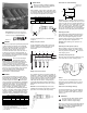
Connection
Insert the plug straight into the receptacle until a
‘
click’ is heard. Figure 1 The plug and its flexible
cable must not exert force on the receptacle.
Pull on the plug to make sure it is properly latched in
the receptacle. Figure 2 A small rotation of the
plug, in either direction, engages the locking finger on
the receptacle to prevent any further rotation.
To close the pilot circuit and mechanically lock the
plug into the receptacle, turn the ring on the recepta-
cle until the “1” lines up with the arrow across from
the release button. Figure 3
D
o not attempt to turn the ring towards “1”
w
hen there is no plug engaged. Defeating the
mechanical lock could create a potentially
h
azardous condition if energized under load.
Disconnection
To open the pilot circuit and unlock the plug, turn the
r
ing back until the “0” is aligned with the arrow.
Figure 4 This action signals the controller to switch
off the power and unlocks the plug. To remove the
p
lug, press firmly on the latch release button and
simultaneously pull on the plug. A slight rotation of
t
he plug may be required before it can be removed.
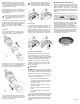
Achieving rated watertightness
Rated IP66 /67 watertightness to is achieved when
the plug and receptacle are mated. When discon-
nected, the receptacle cap must be fully inserted with
the slot in the cap aligned with the protruding ‘button’.
The plug cap must be pressed firmly into place.
NOTICE: Proper steps must be taken to maintain
watertightness at threaded connections on the plug
handles or at the junction box. The use of a sealer
tape is recommended.
MAINTENANCE
WARNING: Before inspecting, repairing, or maintain-
ing Meltric products, disconnect electrical power to
the receptacle to eliminate the risk of electrical shock.
Meltric products require little on-going maintenance.
However, it is a good practice to periodically perform
the following general inspections:
•Check the mounting screws for tightness.
• Verify that the weight of the cable is supported
by the strain relief mechanism and not by the
terminal connections.
• Check the IP gaskets for wear and resiliency.
Replace as required.
• Verify the electrical continuity of the ground
circuit.
• Check the contact surfaces for cleanliness
and pitting.
Use a clean cloth to rub off deposits of dust or similar
foreign materials on the contacts and the plug interiors.
Sprays should not be used, as they tend to collect
dirt. If any significant pitting of the contacts or other
serious damage is observed, the device should be
replaced.
M
ANUFACTURER’S RESPONSIBILITY
Meltric’s responsibility is strictly limited to the repair or
r
eplacement of any product that does not conform to the
w
arranty specified in the purchase contract. Meltric
shall not be liable for any penalties or consequential
d
amages associated with the loss of production, work,
profit, or any other kind of financial loss incurred by the
c
ustomer.
Meltric Corporation shall not be held liable when its
p
roducts are used in conjunction with products not
bearing the
T
M
technology trademark. The
u
se of Meltric products in conjunction with mating
d
evices that are not marked with the
TM
t
ech-
nology trademark shall void all warranties on the product.
Meltric Corporation is an ISO 9001 certified company.
Its products are designed, manufactured and rated in
a
ccordance with applicable UL, CSA and IEC
standards. Meltric is also a member of BECMA, the
i
nternational Butt-contact Electrical Connectors
Manufacturers’ Association. Like all members, Meltric
additionally designs and manufactures its products in
a
ccordance with BECMA standards established to
ensure intermatablility with similarly rated products
m
anufactured by other members.
www.becma.ch
4
3
1
2
Latch
Release
Button
INSSP E