
User manual


Jumper Options 6
519 User Guide
Jumper Options
The 519 may be fitted with up to five internal jumpers which will change
the way it operates. IN ALMOST ALL INSTALLATIONS NONE OF
THESE JUMPERS WILL BE NEEDED. The unit is supplied with no
jumpers fitted. It is recommended that the jumpers are fitted only by your
dealer.
Opening the Case
WARNING: BEFORE OPENING THE CASE DISCONNECT THE 519
FROM THE AC SUPPLY. BEFORE RECONNECTING THE SUPPLY
ENSURE THAT THE CASE IS FULLY REASSEMBLED.
To open the case remove the four screws at the corners of the rear of the
519 and the four screws at the corners of the base of the 519.
Locating the Jumper Positions
There are five sets of two pins each which may be fitted with jumpers.
Jumper number 1 is located on the left of the 519 when viewed from the
front.
Jumper 1
The Laser Disc RF output signal normally provides an 5 Volt DC signal to
indicate that the Disc is playing. When jumper 1 is not fitted the Laser
Disc 5 Volt signal is used by the 519 to enable AC-3 demodulation or
switching to regular digital audio If your Laser Disc player does not give
the 5 Volt signal fit jumper 1.
Jumper 2
In normal use the 519 will switch to regular digital audio if it is unable to
demodulate AC-3. This allows both AC-3 encoded and non AC-3
encoded discs to be replayed with no change of settings by the user.
However, fitting jumper 2 tells the 519 not to switch to regular digital
audio. In this case, if AC-3 cannot be decoded, the 519 will produce a
silent digital audio output at 48kHz sampling rate.
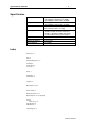
Jumpers 3-5
These jumpers allow the system address for the Meridian 500 Series
Comms to be changed:
System Address
Jumper 3
Jumper 4
Jumper 5
1
2
3
4
5
6
7
8