
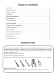
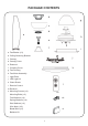
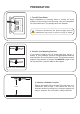
Instructions / Assembly

7
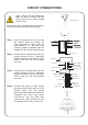
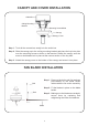
CIRCUIT CONNECTIONS
White (neutral)
Green or Bare
Copper (ground)
White (“AC IN N”)
Outlet Box
Black (hot)
Black (“AC IN L”)
White (neutral)
Blue (light)
Green (ground)
White (neutral)
Black (motor)
Blue (light)
Red (for L)
Receiver
Red (for L)
Orange
(for N)
Black (“to motor L”)
Orange
(for N)
Receiver Head
GREY
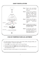
Step 1. Insert the receiver into the tray with
the receiver facing the ceiling. For
best performance, make sure the
white antenna, on the end of the
receiver, remains extended and not
tangled with any of the electrical wires.
Step 2. Connect the 5 colored wires from the
remote receiver to the 5 identically
colored lead wires from the fan motor.
Secure each set with the provided
wire nuts.
Step 3. Connect the 2 colored wires from the
remote receiver to the 2 identically
colored lead wires from the outlet box.
Secure each set with the provided
wire nuts.
Step 4. Connect the green or bare copper
ground wire from the outlet box to the
ground wires from the ceiling
mounting bracket and the ceiling fan.
Separate the white and green
connections from the black wire
connections, which should be kept
on opposite sides of the outlet box.
Ensure there are no loose wires or connections,
and secure connectors with electrical tape.
Again, ensure that the power has
been cut before working with the
wiring. Use the wire nuts provided
with your fan.
Registration Slot