
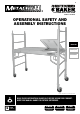
Product Manual


3
ENGLISH
BOX CONTENTS
QTY. PART CODE DESCRIPTION
2 I-CISF Side frames
2 I-CISB Braces
1 I-CISPT Platform
4 I-C1CAS5 Casters
8 I-CAS5PIN Locking pins
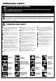
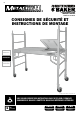
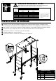
ASSEMBLY INSTRUCTIONS
1
Insert casters in side frame’s lower extremity. Secure casters with locking pins.
Lock the casters by firmly depressing the top tab of the caster.
2
While maintaining the brace locking mechanism pulled, insert the braces onto
the frame sides at desired height.
3
Ensure that the locking stems are properly engaged in side frames.
4
Secure the brace using the locking pins.
5
Install the platform on the braces.
6
Turn the platform security latches toward the inside.
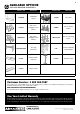
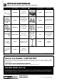
MAXIMUM CLIMBING DISTANCE
TOTAL WEIGHT
(WORKER +
TOOLS)
ONE UNIT HIGH TWO UNITS HIGH OR MORE*
Distance is measured from the farthest body part to the ladder**
150 lb 16.38 in. 31.14 in.
160 lb 15.36 in. 29.19 in.
170 lb 14.46 in. 27.48 in.
180 lb 13.65 in. 25.95 in.
190 lb 12.94 in. 24.58 in.
200 lb 12.29 in. 23.35 in.
210 lb 11.70 in. 22.24 in.
220 lb 11.17 in. 21.23 in.
230 lb 10.69 in. 20.31 in.
Maximum distance to keep from the side frame in order to safely climb a mobile scaffold unit.
The loading condition considered in this table is only the scaffold’s self-weight.
MAX
* The counterweight provided by the
guardrail system and outriggers is not
considered in this calculation.
** No part of the body should extend
farther than the distance mentioned.
1
4
3
5
6
2