
User Guide


An integrated protective circuit automatically
W
arning! Do not press the ON/OFF switch any
more if the protective circuit has actuated. This
may damage the battery.
1. Check that your mains voltage is the same as
that marked on the rating plate of the battery
charger. Plug the battery charger in the plug
socket and connect the charging cable (9) to the
charging socket (6).
2. LED indications (7):
red LED illuminate: beginning charging process
yellow and red LED illuminate: battery is partly
charged all LEDs illuminate: battery is fully
charged.
If the battery pack fails to charge, please check
whether ther
e is voltage at the socket-outlet
and check f
or proper contact with the charging
contacts in the battery charger.
If the battery still fails to charge, send
the ba
ttery charger
and the scr
ewdriv
er
to our customer services department.
Timely recharging of the battery pack will help it
serve you well for a long time. You must recharge
the battery pack when you notice that the power
of the screwdriver drops.
Never allow the battery pack to become fully
discharged. This will cause it to develop a defect.
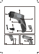
6.2 Changeover switch (Fig. 2/Item 4)
The slide switch above the ON/OFF switch is for
setting the direction of rotation of the cordless
screwdriver and for preventing the cordless
screwdriver from being switched on
inadvertently.
You can select between clockwise and
counterclockwise rotation. Change the direction
of rotation only when the equipment is at a
standstill. If you fail to observe this point, the
gearing may become damaged. When the slide
switch is in the middle position, the ON/OFF
switch is blocked.
6.3 ON/OFF switch (Fig. 2 / Item 3)
scr
ewdriver on. Release the ON/OFF switch to
6.4 LED lamp
T
he LED lamp (5) can be used in poor lighting
conditions to illuminate the area where you want
to screw.
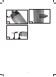
6.5 Torque setting (Fig. 3)
mechanical t
orque select
or.
with the t
orque selector (2). The correct torque
depends on several factors:
on the type and hardness of ma
terial in question
on the t
ype and length screws used
on the r
equirements needing t
o be met by the
screwed joint.
The clutch disengages with a grating sound to
indicate when the set torque is reached.
6.6 Battery capacity indicator (Fig. 4)
The battery capacity indicator (7) indicates the
charge state of the battery on 3 colored LEDs.
All LEDs illuminate:
The battery is fully charged.
The yellow and red LED illuminate:
The battery has an adequate remaining charge.
Red LED:
The battery is empty, recharge the battery.
8