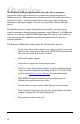
RADIANCE 10MBPS SINGLE INTERFACE LINE CARDS 10BASE 10BASE 10BASE 10BASE PWR PWR PWR PWR TP TP PWR TP TP TP LK LK LK LK LK AT AT AT AT AT BNC FL LK M M T X FL FL R X COL 10BASE R X LK AT T X FL LK S M M M AT R X AT T X Installation & User Guide Models: R111-12 / R111-13 / R111-15 / R111-16 / R111-18 / R111-1T R X M M T X LK AT
Radiance 10Mbps Single Interface Line Cards Copper to Copper: R111-12 ______ RJ-45 to Thinnet Coaxial BNC Copper to Fiber: R111-13 ______ R111-15 ______ R111-16 ______ R111-18 ______ R111-1T ______ RJ-45 to FL multimode SC RJ-45 to FL multimode ST RJ-45 to FL singlemode ST RJ-45 to FL multimode SMA RJ-45 to FL multimode ST (LH) This publication is protected by the copyright laws of the United States and other countries, with all rights reserved.
Table of Contents Radiance 10Mbps Single Interface Line Cards Installation & User Guide Overview ............................................................................................................... 4 Installation Guide ................................................................................................ 5 STEP 1: Unpack the Line Card .............................................................. 5 STEP 2: Set the Jumper ................................................................
Overview The Radiance 10Mbps single interface line cards offer transparent integration of fiber optic connectivity or copper-to-coaxial integration in Ethernet networks. These innovative solutions provide full signal restoration— with low bit delay—ensuring accurate data transmission and guaranteeing maximum cable length support. All cards are compatible with any Ethernet device.
Installation Guide Follow the simple steps outlined in this section to install and start using your Radiance 10Mbps single interface line card. NOTE: Electrostatic discharge precautions should be taken when handling any line card. Proper grounding is recommended (i.e., wear a wrist strap). 1 Unpack the Line Card 2 Set the Jumper Your order has been provided with the safest possible packaging, but shipping damage does occasionally occur. Inspect your line card carefully.
R111-12 Only On the RJ-45 to BNC line card, a jumper is used to set either internal or external termination of the BNC port. See the diagram below to locate the jumper, labeled JP1. • Connect pins 1 and 2 to enable internal 50Ω termination. • Connect pins 2 and 3 to enable use of external termination.
3 Set the MDI-II/MDI-X Switch (twisted-pair ports only) To eliminate the need for crossover cables, the Radiance line cards have an MDI-II to MDI-X slide switch for each twisted-pair port. This switch is positioned directly behind its associated RJ-45 connector and allows simple setup in either straight-through (default) or crossover configurations. See the diagrams on pages 5 and 6 for the location of the switch.
4 Install the Line Card The Radiance 10Mbps single interface line card offers the ease of plugand-play installation and is hot-swappable. The card must be firmly secured to the chassis before network connections are made. Follow the simple steps outlined below to install your line card.
10/100 LK TX x II 100 TX 100 x II TX x II LK LK M M LK RX M M LK TX TX x II FL 100 FD FX FL LK TX LK M M 10/100 PWR LK MGT-10 PWR FL 100 LK FD RX RX RX T X LK 10/100 PWR FL FD RX LK RX 1 RX LK M M LK AT R X M M T X TX TX LK RX AT M M LK TX M M TX x II TX RX R X LK S M LK TX T X TX LK LK LK x II TX TX TX x II AT TX PWR RX RX M M LK LK M M LK M M LK M M LK RX M M LK TX TX TX TX RX RX RX RX M M TX TX FX FX
User Guide This section contains information about the operating features of the Radiance 10Mbps single interface line cards. LED Indicators The Radiance 10Mbps single interface line cards provide several LEDs for the visible verification of unit status and proper functionality. These LEDs can help with troubleshooting and overall network diagnosis and management. There are separate activity (AT) and link (LK) indicators for each port.
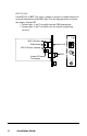
Link Loss Carry Forward (LLCF)* The Radiance 10Mbps single interface line cards incorporate an LLCF function for troubleshooting a remote connection. When LLCF is enabled, the FL and TP ports do not transmit a link signal until they receive a link signal from the opposite port. The diagram below shows a typical network configuration with a good link status using Radiance line cards for remote connectivity. Note that LLCF is enabled as indicated in the diagram.
Technical Specifications Data Rate Data Rate ______________________ 10Mbps half duplex; 20Mbps full duplex Bit Delay __________________________________________________ < 5 bits Environmental Power ___________________________________ 5V @ 1.
Multimode F/O Interface (R111-13, R111-15, R111-18) Connector __________________________________________ SC, ST or SMA Wavelength _________________________________________________ 820nm RX Input Sensitivity ______________________________ -32.5 dBm minimum Output Power ______________________ -21.8 dBm to -16.8 dBm (50/125 µm) _______________________ -19 dBm to -14 dBm (62.
Product Safety, EMC and Compliance Statements This equipment complies with the following requirements: • UL • CSA • EN60950 (safety) • FCC Part 15, Class A • EN55022 Class A (emissions) • EN55024: 1998 (immunity) • IEC 825-1 Classification • Class 1 Laser Product • DOC Class A (emissions) • CB This product shall be handled, stored and disposed of in accordance with all governing and applicable safety and environmental regulatory agency requirements.
Warranty and Servicing Three-Year Warranty for Radiance 10Mbps Single Interface Line Cards Metrobility Optical Systems, Inc. warrants that every Radiance 10Mbps single interface line card will be free from defects in material and workmanship for a period of THREE YEARS from the date of Metrobility shipment. This warranty covers the original user only and is not transferable.
Product Manuals The most recent version of this manual is available online at http://www.metrobility.com/support/manuals.htm Product Registration To register your product, go to http://www.metrobility.com/support/registration.asp 25 Manchester Street, Merrimack, NH 03054 USA tel: 1.603.880.1833 • fax: 1.603.594.2887 www.metrobility.