METROLOGIC INSTRUMENTS, INC.
Copyright © 2008 by Metrologic Instruments, Inc. All rights reserved. No part of this work may be reproduced, transmitted, or stored in any form or by any means without prior written consent, except by reviewer, who may quote brief passages in a review, or provided for in the Copyright Act of 1976. Trademarks Metrologic is a registered trademark of Metrologic Instruments, Inc. Products identified in this document are hereby acknowledged as trademarks, registered or otherwise, of Metrologic Instruments, Inc.
TABLE OF CONTENTS Introduction Product Overview ............................................................................................. 1 Scanner and Accessories................................................................................. 2 Scanner Components....................................................................................... 4 Cable Removal................................................................................................. 4 Caution and Serial Number Labels........
TABLE OF CONTENTS Default Settings - Communication Parameters................................................... 25 Scanner Configuration.................................................................................... 30 Configuration Modes ...................................................................................... 30 Bar Codes .................................................................................................. 30 MetroSet2........................................................
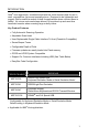
INTRODUCTION ® Orbit is an aggressive, omnidirectional laser bar code scanner ideal for use in retail, convenience, liquor and specialty stores Designed to be lightweight and rugged, Orbit’s small size makes it ideal for applications where counter space is limited. It’s unique contoured shape allows it to be picked-up and used as a hand-held scanner when scanning large or bulky items.
INTRODUCTION Scanner and Accessories BASIC KIT COMPONENTS Part No. Description MS7120 Orbit Presentation Laser Bar Code Scanner 00-02282x MS7120 Orbit Presentation Laser Bar Code Scanner Installation and User’s Guide 00-02407x MetroSelect® Configuration Guide * Guides also available for download at www.metrologic.com. OPTIONAL ACCESSORIES Part No. Description AC to DC Power Transformer - Regulated 5.2VDC @ 1A output.
INTRODUCTION Scanner and Accessories OPTIONAL ACCESSORIES Part No. Description RS485S Applications Metrologic Voltage Converter Cable ±12VDC to +5.2VDC MVC** ** Contact a Metrologic customer service representative for additional information on the MVC cable series and the host connections available.
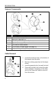
INTRODUCTION Scanner Components ITEM NO 1 2 DESCRIPTION White LED (see page 12) Blue LED (see page 12) 3 Red Output Window (Laser Aperture) 4 Speaker (see page 12) 5 6 7 Pin Hole for Cable Release 10-Pin RJ45, Female Socket (see page 33) Adjustable Scan Head, 30° Figure 1. Scanner Components Cable Removal Figure 2. Cable Release 4 1. Locate the small ‘pin-hole’ on the bottom of the scanner near the cable. 2. Bend an ordinary paperclip into the shape shown. 3.
INTRODUCTION Caution and Serial Number Labels Figure 3. Labeling Locations on the Bottom of the Scanner and Examples Caution To maintain compliance with applicable standards, all circuits connected to the scanner must meet the requirements for SELV (Safety Extra Low Voltage) according to EN/IEC 60950-1. To maintain compliance with standard CSA C22.2 No. 60950-1/UL 60950-1 and norm EN/IEC 60950-1, the power source should meet applicable performance requirements for a limited power source.
INTRODUCTION Mounting Specifications Optional Wall/Counter Mount Item Description Qty. a. Locking Plate, MLPN 50-50302 1 b. Base Cover, MLPN 50-50301 1 c. #7 x 1.00" Wood Screw, MLPN 18-18013 3 d. M3 x 8 mm Flathead Screw, MLPN 18-18004 4 Figure 4. Kit Components 1. Drill three #39 pilot holes. Note the position Orbit will rest (see Figure 5). Use the dimensions provided in Figure 5 or the locking plate as a template to drill three #39 pilot holes in the mounting surface. 2.
INSTALLATION RS232, Light Pen Emulation 1. Turn off the host device. 2. Plug the male 10-pin RJ45 end of the PowerLink cable into the 10-pin socket on the MS7120. 3. Connect the 9-pin female end of the PowerLink cable to the host device. 4. Plug the external power supply into the power jack on the PowerLink cable. Check the AC input requirements of the power supply to make sure the voltage matches the AC outlet. The outlet must be located near the equipment and be easily accessible. 5.
INSTALLATION RS485S 1. Turn off the host device. 2. Plug the male 10-pin RJ45 end of the MVC cable into the 10-pin socket on the MS7120. 3. Connect the other end of the MVC cable to the host device. 4. Turn on the host device. Figure 10. When the scanner first receives power, the blue and white LED will toggle on and off then the scanner will beep once. Plugging the scanner into the serial port of the PC does not guarantee that scanned information will appear at the PC.
INSTALLATION Keyboard Wedge 1. Turn off the host device. 2. Plug the male 10-pin RJ45 end of the PowerLink cable into the 10-pin socket on the MS7120. 3. Disconnect the keyboard from the host device. 4. Connect the “Y” end of the PowerLink cable to the keyboard and the keyboard port on the host PC. If necessary use the male/female adapter cable supplied with the scanner for proper connections. 5. Plug the external power supply into the power jack on the PowerLink cable.
INSTALLATION Stand-Alone Keyboard 1. Turn off the host device. 2. Plug the male 10-pin RJ45 end of the PowerLink cable into the 10-pin socket on the MS7120. 3. Connect the other end of the PowerLink cable to the keyboard port on the host device. 4. Plug the external power supply into the power jack on the PowerLink cable. Check the AC input requirements of the power supply to make sure the voltage matches the AC outlet. The outlet must be located near the equipment and be easily accessible. 5.
INSTALLATION Full Speed or Low Speed USB 1. Turn off the host device. 2. Plug the male 10-pin RJ45 end of the USB cable into the 10-pin socket on the MS7120. 3. Plug the other end of the USB interface cable into the host device’s USB port. 4. Turn on the host device. When the scanner first receives power, the blue and white LED will toggle on and off then the scanner will beep once. Figure 13. As a default, the MS7120-38 leaves the factory with USB Keyboard Emulation Mode enabled.
SCANNER OPERATION Audible Indicators When the MS7120 is in operation, it provides audible feedback to indicate the status of the scanner. Eight settings are available for the tone of the beep (normal, six alternate tones and no tone). For instructions on how to change the tone of the beeper, refer to the MetroSelect Configuration Guide (00-02407). One Beep When the scanner first receives power the blue and white LED will toggle on and off.
SCANNER OPERATION Visual Indicators The MS7120 is equipped with a blue and a white LED that indicates the scanner’s state and the status of the current scan when the unit is in operation. Figure 14. LED Location No LEDs The LEDs will not be illuminated if the scanner is not receiving power from the host or transformer. Steady Blue When the laser is active, the blue LED is illuminated. The blue LED will remain on until the laser is deactivated. During the power save mode, the laser will turn on and off.
SCANNER OPERATION Failure Mode Indicators Flashing Blue with One Razzberry Tone This indicates that the scanner has experienced a laser subsystem failure. Return the unit to an authorized service center for repair. Synchronized Flashing of Blue and White with Two Razzberry Tones This indicates that the scanner has experienced a motor failure. Return the unit to an authorized service center for repair.
SCANNER OPERATION Depth of Field Specifications* Normal Scan Zone Specifications are based on a 0.33 mm (13 mil) bar code. Figure 15. MS7120 Normal Depth of Field Reduced Scan Zone Specifications are based on a 0.33 mm (13 mil) bar code. Figure 16. MS7120 Reduced Depth of Field * All specifications are subject to change without notice.
SCANNER OPERATION Depth of Field by Bar Code Element Width* Normal Scan Zone MINIMUM BAR CODE ELEMENT WIDTH A B C D E F G H J K mm .13 - - - .19 - .25 .33 - .66 mils 5.2 - - - 7.5 - 10 13 - 26 Figure 17. Normal Scan Zone by Bar Code Element Width * All specifications are subject to change without notice.
SCANNER OPERATION Depth of Field by Bar Code Element Width* Reduced Scan Zone MINIMUM BAR CODE ELEMENT WIDTH A B C D E F G H J K mm - .15 - - .19 - .25 .33 - .66 mils - 5.7 - - 7.5 - 10 13 - 26 Figure 18. Reduced Scan Zone by Bar Code Element Width * All specifications are subject to change without notice.
TROUBLESHOOTING GUIDE The following guide is for reference purposes only. Contact a Metrologic representative at 1-800-ID-METRO or 1-800-436-3876 to preserve the limited warranty terms on page 38. Symptoms Possible Cause(s) Solution All Interfaces During power up the unit beeps three times. There is a non-volatile RAM failure. Contact a Metrologic service representative. During power up the unit razzes once and the blue LED flashes. There is a VLD failure.
TROUBLESHOOTING GUIDE Symptoms Possible Cause(s) Solution All Interfaces The unit is trying to scan a particular symbology that is not enabled. The unit powers up but does not scan and/or beep. The scanner has been configured for a character length lock, or a minimum length and bar code being scanned does not satisfy the configured criteria. UPC/EAN, Code 39, Interleaved 2 of 5, Code 93, Code 128 and Codabar are enabled by default.
TROUBLESHOOTING GUIDE Symptoms Possible Cause(s) Solution All Interfaces Scanner beeps at some bar codes and NOT for others of the same bar code symbology. The bar code may have been printed incorrectly. Check if it is a check digit, character or border problem. The scanner is not configured correctly for the type of bar code. Check if check digits are set properly. The minimum symbol length setting does not work with the bar code. Check if the correct minimum symbol length is set.
TROUBLESHOOTING GUIDE Symptoms Possible Cause(s) Solution RS232 Only The host is The scanner and host receiving data may not be configured but the data does for the same interface. not look correct. Characters are being dropped. The inter character delay needs to be added to the transmitted output. Check that the scanner and the host are configured for the same interface. Add some inter-character delay to the transmitted output by using the MetroSelect Configuration Guide (MLPN 00-02407).
DESIGN SPECIFICATIONS MS7120 Operational Light Source: Visible Laser Diode (VLD) @ 650 nm Laser Power: Less than 1 mW average Normal Depth of Field: 0 mm – 215 mm Reduced Depth of Field: 0 mm – 190 mm Scan Speed: No. of Scan Lines: Motor Speed: Min Bar Width: 0.33 mm (13 mil) bar code 1120 scan lines per second 20 3360 RPM 0.13 mm (5.
DESIGN SPECIFICATIONS MS7120 Electrical Voltage Supply: Operating Power: Standby Power: 5VDC ± 0.25V 0.9 W 0.85 W Operating Current: 180 mA typical at 5VDC Standby Current: 170 mA typical at 5VDC DC Transformers: Class II; 5.2VDC @ 1A For regulatory compliance information, see pages 35 - 37.
APPLICATIONS AND PROTOCOLS The model number on each scanner includes the scanner number and factory default communications protocol. SCANNER VERSION IDENTIFIER 38 RS232 Low Speed USB, Keyboard Emulation or Serial Emulation 41 Full RS232C/Light Pen Emulation 47 Keyboard Wedge, Stand-Alone Keyboard and RS232 Transmit/Receive 106 RS485S and Full Speed USB MS7120 S COMMUNICATION PROTOCOL(S) ® Applicable for IBM Host applications.
DEFAULT SETTINGS - COMMUNICATION PARAMETERS Many functions of the scanner can be "configured" - that is enabled or disabled. The scanner is shipped from the factory configured to a set of default conditions. The default parameter of the scanner has an asterisk ( * ) in the charts on the following pages. If an asterisk is not in the default column then the default setting is Off or Disabled. Every interface does not support every parameter.
DEFAULT SETTINGS - COMMUNICATION PARAMETERS PARAMETER DEFAULT * Expanded ID “]e0” RSS Limited Enable RSS Limited ID “]e0” * RSS Limited App ID “01” * RSS Limited Check Digit * Bars High as Code 39 * Spaces High as Code 39 Bars High as Scanned Spaces High as Scanned DTS/SIEMENS * DTS/NIXDORF NCR F NCR S Poll Light Pen Source Beeper Tone Normal Beep/Transmit Sequence Before Transmit Communication Timeout None Razzberry Tone on Timeout Three Beeps on Timeout * No Beeps on Timeout Enter Pow
DEFAULT SETTINGS - COMMUNICATION PARAMETERS PARAMETER DEFAULT Transmit UPC-A Check Digit RS232 LIGHT PEN RS485S KBW USB * Transmit UPC-E Check Digit Expand UPC-E Convert UPC-A to EAN-13 Transmit Lead Zero on UPC-E Convert EAN-8 to EAN-13 Transmit UPC-A Number System * Transmit UPC-A Manufacturer ID# * Transmit UPC-A Item ID# * Transmit Codabar Start/Stop Characters CLSI Editing (Enable) Transmit Mod 43 Check Digit on Code 39 Transmit Code 39 Stop/Start Characters Transmit Mod 10/ITF Transmit
DEFAULT SETTINGS - COMMUNICATION PARAMETERS PARAMETER DEFAULT RS232 LIGHT RS485S PEN KBW USB Nixdorf ID LRC Enabled UPC Prefix UPC Suffix Transmit AIM ID Characters STX Prefix ETX Suffix Carriage Return * Line Feed - disabled by default in KBW * Tab Prefix Tab Suffix “DE” Disable Command Serial Emulation Mode Only “FL” Laser Enable Command Serial Emulation Mode Only DTR Handshaking Support RTS/CTS Handshaking * Character RTS/CTS Message RTS/CTS XON/XOFF Handshaking Serial Emulation Mode Onl
DEFAULT SETTINGS - COMMUNICATION PARAMETERS PARAMETER DEFAULT Supplements are not Required * Two Digit Redundancy * RS232 LIGHT RS485S PEN KBW USB Five Digit Redundancy 100 msec to Find Supplement Configurable in 100msec steps (MAX 800 msec) * as code 39 Coupon Code 128 Configurable Code Lengths 7 avail. Configurable Prefix Characters 10 avail. Configurable Suffix Characters 10 avail.
SCANNER CONFIGURATION CONFIGURATION MODES The MS7120* Series scanner has three modes of configuration. • Bar Codes The MS7120 can be configured by scanning the bar codes included in the MetroSelect Configuration Guide (MLPN 00-02407). These manuals can be downloaded FREE of charge from Metrologic’s website (www.metrologic.com). • MetroSet2 This user-friendly Windows-based configuration program allows the enduser to simply ‘point-and-click’ at the desired scanner options.
UPGRADING THE FIRMWARE The MS7120 is part of Metrologic's line of scanners with flash upgradeable firmware. The upgrade process requires, a new firmware file supplied to the customer by a customer service representative and Metrologic's MetroSet2 software. A personal computer running Windows 95 or greater with an available RS232 serial or USB port is required to complete the upgrade. PowerLink Cable #54-54014 is required when using RS232 for the upgrade process.
SCANNER AND CABLE TERMINATIONS Scanner Pinout Connections The MS7120 scanner interfaces terminate to a 10-pin modular socket. The serial number label indicates the interface enabled when the scanner is shipped from the factory. Figure 19.
SCANNER AND CABLE TERMINATIONS Cable Connector Configurations (Host End) “Standard” PowerLink Cable MLPN 59-59000x -3 straight Pin Function 1 Shield Ground 2 RS232 Transmit Output 3 RS232 Receive Input 4 DTR Input/Light Pen Source 5 Power/Signal Ground 6 Light Pen Data 7 CTS Input 8 RTS Output 9 +5VDC 9-Pin D-Type Connector USB Power/Communication Cable MLPN 54-54213x-N-3, 54-54214x-N-3 or 59-59235x-N-3 Pin Function 1 PC +5V/V_USB 2 D- 3 D+ 4 Ground Shield Shield Locking, Type
SCANNER AND CABLE TERMINATIONS Cable Connector Configurations (Host End) Keyboard Wedge PowerLink Cable 59-59002x -3 Pin 1 2 3 4 5 Pin 1 2 3 4 5 6 Function Keyboard Clock Keyboard Data No Connect Power Ground +5 Volts DC Function PC Data No Connect Power Ground +5 Volts DC PC Clock No Connect 5-Pin DIN, Female 6-Pin DIN, Male Metrologic will supply an adapter cable with a 5-pin DIN male connector on one end and a 6-pin mini DIN female connector on the other.
REGULATORY COMPLIANCE Safety ITE Equipment IEC 60950-1, EN 60950-1 Laser Laser Class 1: IEC 60825-1:1993+A1+A2, EN 60825-1:1994+A1+A2 Caution Use of controls or adjustments or performance of procedures other than those specified herein may result in hazardous laser light exposure. Under no circumstances should the customer attempt to service the laser scanner. Never attempt to look at the laser beam, even if the scanner appears to be nonfunctional.
REGULATORY COMPLIANCE EMC Emissions: FCC Part 15, ICES-003, CISPR 22, EN 55022 Immunity: CISPR 24, EN 55024 Changes or modifications not expressly approved by the party responsible for compliance could void the user’s authority to operate the equipment. Class A Devices The following is applicable when the scanner cable is greater in length than 3 meters (9.8 feet) when fully extended: Les instructions ci-dessous s’appliquent aux cables de scanner dépassant 3 métres (9.
REGULATORY COMPLIANCE EMC Changes or modifications not expressly approved by the party responsible for compliance could void the user’s authority to operate the equipment. Class B Devices The following is applicable when the scanner cable is less than 3 meters (9.8 feet) in length when fully extended: Les instructions ci-dessous s’appliquent aux cables de scanner ne dépassant pas 3 métres (9.
LIMITED WARRANTY The MS7120 Orbit® scanners are manufactured by Metrologic at its Suzhou, China facility. The MS7120 Orbit scanners have a three (3) year limited warranty from the date of manufacture. Metrologic warrants and represents that all MS7120 Orbit scanners are free of all defects in material, workmanship and design, and have been produced and labeled in compliance with all applicable U.S. Federal, state and local laws, regulations and ordinances pertaining to their production and labeling.
PATENTS Patent Information This METROLOGIC product may be covered by, but is not limited to, one or more of the following U.S. Patents: U.S. Patent No.
INDEX A host ....................................... 18–21 AC .................................. see power accessories ...............................2, 3 adapter ....................................9, 34 I B bar code ......................................30 bar width......................................22 beep ............................see indicator blue .............................see indicator C cable communication. 2, 3, 4, 7–11, 33– 34 pin assignments........... 32, 33–34 caution...............
INDEX P patents.........................................39 pin assignments cable ..................................33–34 scanner ....................................32 port .............................. 7–11, 18–21 power .................. 2, 3, 7–11, 22, 23 PowerLink........................ see cable protocol........................................24 R razz .............................see indicator RMA ............................................38 RS232 ........................ see interface RS485 .....
42
May 2008 Printed in the USA 00 - 02282D