
All in One Printer User Manual


4
INTRODUCTION
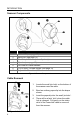
Scanner Components
ITEM NO
DESCRIPTION
1 White LED (see page 12)
2 Blue LED (see page 12)
3 Red Output Window (Laser Aperture)
4 Speaker (see page 12)
5 Pin Hole for Cable Release
6 10-Pin RJ45, Female Socket (see page 33)
7 Adjustable Scan Head, 30°
Figure 1. Scanner Components
Cable Removal
1. Locate the small ‘pin-hole’ on the bottom of
the scanner near the cable.
2. Bend an ordinary paperclip into the shape
shown.
3. Insert the paperclip into the small ‘pin-hole’.
4. There will be a faint ‘click’ when the cable
lock is released. Pull gently on the strain-
relief of the PowerLink cable to remove it
from the scanner.
Figure 2. Cable Release