www.apc.com / www.mgeups.
www.apc.com / www.mgeups.
www.apc.com / www.mgeups.com Table of Contents 1 Introduction to the MGE’s Network Solution ....................................................................... 4 1.1 1.2 1.3 1.4 Overview ...............................................................................................................................................4 Monitoring the UPSs over the network..................................................................................................5 Protecting the computers / servers ..
www.apc.com / www.mgeups.com 7.5.1 7.5.2 7.5.3 7.5.4 7.6 7.7 7.8 Single UPS Shutdown Sequence........................................................................................................44 Multi UPS shutdown sequence (example with Static Transfer Switch) ..............................................46 Additional information on events and actions......................................................................................47 7.8.1 7.8.2 7.8.3 7.8.4 7.8.5 7.9 8 9 Introduction ......
www.apc.com / www.mgeups.com 1 Introduction to the MGE’s Network Solution 1.1 Overview MGE’s Network Solution: ω provides information on events concerning the supply of power to the computers connected to your computer network, ω carries out automatic shutdown of computer systems, ω monitors and controls all the UPSs connected to the network.
www.apc.com / www.mgeups.com 1.2 Monitoring the UPSs over the network Depending on your needs, you can either use: T H E U N I N T E R R U P T I B L E ω your Internet browser to monitor each UPS, as Management Proxy, Management Card and Shutdown Module include a Web server.
www.apc.com / www.mgeups.com 1.3 Protecting the computers / servers The Network Shutdown Module installed on each of the servers to be protected performs this function. Note that the Shutdown Module is available on several Operating Systems. The Shutdown modules: ω continuously wait for information from the Mgt. Proxy or Mgt. Card connected to the MGE UPS. ω warns administrators and users if AC power fails and proceeds with graceful system shutdown before the end of battery backup power is reached.
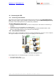
www.apc.com / www.mgeups.com 1.4 Connecting the UPS 1.4.1 Connecting to the Network This function can be performed either through network Cards inserted in the UPS (Network Management Card) or through a software “agent” running on a nearby PC that is called the Network Management Proxy. Note that the Network Management Proxy is available only on Windows.
www.apc.com / www.mgeups.com Connection with Network Management Proxy On the diagram above, three types of connections are required: ω a point-to-point link (serial or USB), ω the electrical power cables, ω the TCP/IP communication network. 1.4.
www.apc.com / www.mgeups.com 2 Installation Note: This user manual only applies to Network Shutdown Module V3. For previous versions of Network Shutdown Module V2.x, please read the HTML on line manual. 2.1 Hardware Pre-requisites (Electrical and Network Connections) Connection steps Before connecting the UPS, you must first decide on a software and hardware architecture. Before installing the MGE Network Solution, the UPS must be set up as indicated in the steps below.
www.apc.com / www.mgeups.com 2.2 2.2.1 Software Installation Pre-requisites On the System Hosting « Network Shutdown Module V3 » 2.2.1.
www.apc.com / www.mgeups.com ω ω 4679 MGESupervision 4680 MGEManagement (access through SSL) These ports are reserved for MGE UPS SYSTEMS at IANA (Internet Assigned Numbers Authority, http://www.iana.org/).
www.apc.com / www.mgeups.com 2.3 Quick Start To install the Network Shutdown Module in 5 minutes, please perform the following steps on a machine running Windows 2000 / XP / 2003 / Vista or Linux: ω Step 1 (Pre-requisites) Check that following connections are operational: > the electrical connection between the UPS and the server to protect > the network connection between the UPS and the Network Management Card (or Proxy).
www.apc.com / www.mgeups.com 2.4 Software Installation Procedure This section informs on how to install Network Shutdown Module to protect the computer system. Before starting the installation: ω it is necessary first to install a Network Management Card in the UPS or the Mgt. Proxy on a server. ω make sure you have the necessary administrator rights to install Network Shutdown Module (for Windows and Linux). ω it is assumed that you are aware of the installation prerequisites.
www.apc.com / www.mgeups.com Configuration of the communication parameters ω Configure your password (recommended) ω For multi-UPS systems, please refer to the chapter "Multi UPS systems" . ω The Network Shutdown Module is now configured by default. You can anyway customize the Network Shutdown Module and for example configure your password (recommended). ω The installed components are automatically started. ω It is possible to test Network Shutdown Module.
www.apc.com / www.mgeups.com 2.5 Application deployment and silent installation (advanced) After customizing the Network Shutdown Module configuration (name or IP address of Network Management Card/Proxy, events and actions, etc.), you can build a Network Shutdown Module installation package that contains your specific configuration. You can then deploy this Network Shutdown Module configuration on other machines that have the same operating system.
www.apc.com / www.mgeups.com 3 Minimal configuration steps 3.1 Introduction In this chapter we describe the basic and minimal configuration steps that must be performed before using the Network Shutdown Module. The other and optional configuration possibilities are described later. 3.2 The IP address of the UPS that powers your server.
www.apc.com / www.mgeups.com Load shedding configuration on UPS powershare outlets Remark: This load shedding function is not available if the UPS doesn’t have any switchable outlet. Note: For multi-UPS configurations, you have the possibility to enter several names or IP addresses (using the [Add] button). For these advanced configurations, please refer to the Chapter « Multi – UPS systems ».
www.apc.com / www.mgeups.com 3.3 Users accounts configuration Click on the Users item of the Configuration section on the left menu. The default Login «MGEUPS» and default Password «MGEUPS» with Visualization – Management rights. Note : For security reasons we advise you to remove this default login and to create a new login with new access password. User accounts configuration You can configure several user accounts.
www.apc.com / www.mgeups.com 4 Use 4.1 Monitoring the server and the UPS(s) 4.1.
www.apc.com / www.mgeups.com ω Enter the Login and Password (optional) ω The following page appears: Server and UPS supervision Section « Information on the protected server» ω Server name / IP address: The Network name of the machine hosting the Network Shutdown Module and its IP address. ω Operating system: The operating system of the machine hosting the Network Shutdown Module.
www.apc.com / www.mgeups.com ω Contact / Location: Status ω Communication: ω Power source: ω Battery: ω Output: Values ω Output Load Level: ω Battery capacity: ω Backup time: The device contact. (value of syscontact object or can also be configured in the Device page). The device location. (value of syslocation object or can also be configured in the Device page). Device communication status (OK / Network Communication Failure / device Communication Failure). AC Power / Battery.
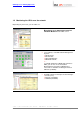
www.apc.com / www.mgeups.com 4.2 System and UPS event log In the Supervision section, Select the Log item, and the following page appears: Network Shutdown Module event Log Use the filter in the top right to choose the data to display: ω All: Displays all the logs. ω UPS logs: Only displays the UPS events. ω System logs: Only displays the System events. ω Use the Export … ω Use the Clear… 4.3 button to record the displayed data into a CSV file. button to clear the displayed data.
www.apc.com / www.mgeups.com Warning. A problem has occurred on the device. Your application is still powered. Event list: ω ω ω ω ω The system is powered by the UPS battery. Output on automatic bypass. Output on manual bypass. Protection lost Redundancy lost (for multi-UPS systems) Critical. A serious problem has occurred on the device. This problem requires an urgent action. Your application might NOT BE powered anymore. Event list: ω ω ω ω ω ω ω ω UPS output is off. Battery fault. UPS overload.
www.apc.com / www.mgeups.com 4.4 Test the communication with the UPS After the installation, it is important to check that Network Shutdown Module communicates with the agent (Mgt. Proxy or the Network Management Card). 4.4.1 Simple Tests Test 1: When Network Shutdown Module starts, an icon is displayed by default in the task bar, if you’re running Windows or Linux (Gnome or KDE).
www.apc.com / www.mgeups.com 4.4.2 Advanced tests For test purpose, it is also possible to display the messages in verbose mode and check the content. Messages in verbose mode: ω Event log: It is possible to consult the Event log. ω Advanced trace: We warn you against the use of disk space for this Trace mode. To validate verbose mode : > in the bin/dae and bin/netsystray directory of the application, rename the file called debugMode.off into debugMode.
www.apc.com / www.mgeups.com 5 Other Configuration possibilities 5.1 Introduction Basic configuration steps are described before (refer to Power devices and Users). In this chapter we describe other configuration possibilities. 5.2 Configure system parameters Click on the System item of the Configuration section on the left menu System parameters configuration This page lets you enter the system parameters for the application. It contains: ω The system administrator name. ω The system localisation.
www.apc.com / www.mgeups.com 5.3 Shutdown Configuration Shutdown Configuration page From this screen, you can define the following parameters: ω Use central configuration provided by Management Card/Proxy: With this function, all the Network Shutdown Modules will obtain their configuration from the card (or proxy).
www.apc.com / www.mgeups.com the client is not guaranteed (the case where AC power returns and only the client station is shut down). ω Message broadcast to the administrator A message is sent over the network to administrators connected to the server protected by Network Shutdown Module. Check following Windows pre-requisite > Default value : activated ω Message broadcast to users A message is sent over the network to users connected to the server protected by Network Shutdown Module.
www.apc.com / www.mgeups.com 5.4 Checking for Upgrades This function gives you access to MGE UPS SYSTEMS software updates. Your Enterprise Power Manager will always be up to date if you select the Check automatically option. When a new software version is detected on www.mgeups.com, just follow the wizard instructions. Note: This operation will preserve your database information.
www.apc.com / www.mgeups.com 5.5 Events and actions (advanced configuration) Basic principles: Network Shutdown Module receives events (e.g. Utility Failure) from the UPS and in reply to these events executes actions (e.g. notification, e-mail, etc.). The above interface allows links between events and actions to be configured, as well as customizing protection for the machine hosting Network Shutdown Module.
www.apc.com / www.mgeups.com 6 Multi-UPS Systems 6.1 Caution Please check complete list of UPSs compatible with our Redundancy/Parallel mode service: Caution: We strongly recommend you contact trained MGE personnel for setup, in order to guarantee the integrity of your high-availability system. Recommendations: ω For the UPS Models it is better to Enable "Communication Shutoff orders" so that the UPS accepts Network Management Card off commands.
www.apc.com / www.mgeups.com ω ω 2 UPSs in serial redundancy: ω 2 unitary UPSs through Static Transfer Switch: ω UPSs powering a server with multiple power supplies: Some simple combinations of these electrical associations are also supported by Network Shutdown module. Important: To know the list of multi-UPS configurations that are supported by the Network Shutdown Module, please refer to the appendix List of tested multi-UPS configurations.
www.apc.com / www.mgeups.com Server and multi-UPS supervision Following information is displayed: Information on the protected server section ω Server name / IP address: the Network name of the machine hosting the Network Shutdown Module and its IP address. ω Operating system: the Operating System name of the machine hosting the Network Shutdown Module.
www.apc.com / www.mgeups.com 6.3 Create a multi-UPS configuration For the multi-UPS configurations, you have to enter the IP address of each UPS that electrically powers the machine hosting the Network Shutdown Module. From the, Configuration->Communication page, please proceed as follows: Multi-UPS configuration ω ω ω ω Click on the Add button Key in the first IP address Key in the next IP addresses (Click on the Add button).
www.apc.com / www.mgeups.com 7 Appendix 7.1 Single UPS Mode compatibility 7.1.1 Card/Proxy compatibility In single UPS Mode, Network Shutdown Module V3 is compatible with following cards/Proxy: ω Network Management Card Transverse 66074 ω Network Management Proxy V5 7.1.
www.apc.com / www.mgeups.com ω 2 UPSs in Hot-Standby: 3 Phase Galaxy 3000 Galaxy 5000 Galaxy PW Note: Specific configuration for 2 UPSs in Hot standby (Sequential redundancy).
www.apc.com / www.mgeups.com 7.2.3 ω Simple associations of the previous configurations Servers with single power supply (and Multiple STS): 3 Phase Galaxy 5000 Galaxy 3000 (without synchro ) Galaxy PW STS Upsilon Notes: ω This configuration has also been tested with 3 STSs ω The Network Shutdown Module V3 is NOT compatible with a configuration where UPS1 and UPS2 are replaced by 2 groups of UPSs.
www.apc.com / www.mgeups.com 7.2.
www.apc.com / www.mgeups.com 7.
www.apc.com / www.mgeups.com 7.5 Application deployment and silent installation 7.5.
www.apc.com / www.mgeups.com 7.5.2 Customized installation package After having customized the Network Shutdown Module configuration (name or IP address of Network Management Card/Proxy, events and actions, etc.), you can build a Network Shutdown Module installation package which contains your specific configuration. You can then deploy this Network Shutdown Module configuration on other machines which have the same operating system.
www.apc.com / www.mgeups.com 7.5.3 Install the Shutdown Module in silent mode In addition to Network Shutdown Module installation in standard mode where the user configures the parameters during the installation, it is possible to install Network Shutdown Module in silent mode i.e. with no user interaction. Follow these steps to install Network Shutdown Module in silent mode: ω Make sure you have administrator rights.
www.apc.com / www.mgeups.com 7.5.
www.apc.com / www.mgeups.com 7.6 Single UPS Shutdown Sequence Typical example of the backup time provided by a UPS connected to Network Management Card: 1 As soon as it detects the loss of AC power, the Mgt. Card notifies the Network Shutdown Modules that the system is running on battery power. 2 The Mgt. Card then continuously monitors the criteria set to trip the shutdown procedure. The procedure is launched if: 1.
www.apc.com / www.mgeups.com Example A UPS protects 3 machines hosting a Network Shutdown Module. Machine 3 is programmed to shut down before the others to take some of the load off the UPS. Machine 1 Machine 2 Machine 3 None None 100 sec 120 sec 60 sec 180 sec Shutdown timer Shutdown duration The main output shutdown duration is equal to 180 sec. It is the shutdown duration of the machine 2 (maximum of all the shutdown duration).
www.apc.com / www.mgeups.com 7.7 Multi UPS shutdown sequence (example with Static Transfer Switch) Typical example of the backup time provided by 2 UPSs in redundancy through Static Transfer Switch. ω The Output load level of the first UPS is less than 50 %. ω The Output load level of the second UPS is 0 %. 1 As soon as they detect the loss of AC power, the Mgt. Cards notify the Network Shutdown Modules that the system is running on battery power.
www.apc.com / www.mgeups.com 7.8 Additional information on events and actions 7.8.1 Action settings Tab In the Action settings tab you can configure the actions that are executed by the Network Shutdown Module. Action settings tab Select an action in the Action List (eg. User Notification) then you have the possibility to select the different tabs for the considered action: ω In the “Settings” tab, you can configure the selected action that is executed by the Network Shutdown Module.
www.apc.com / www.mgeups.com 7.8.1.1 The different actions There are several actions classified into two categories: ω Standard actions By default, Network Shutdown Module only uses these actions to ensure the machine's protection and to inform users. ω Customized actions These user-customized actions give access to additional functions.
www.apc.com / www.mgeups.com 7.8.1.3 «System Shutdown» Action When personalizing the action System shutdown in the action configuration page, you can choose the type of shutdown: ω ω For Windows, there is a choice of shutdown depending on your system and your requirements. Click on the Parameter button, to read the help on the shutdown type: For Linux, only the shutdown option is currently supported. Shutdown parameters ω Shutdown (-shutdown: default selection).
www.apc.com / www.mgeups.com 7.8.1.4 Execute Action Follow these steps to create an action « Execute a program »: Action settings tab Click on the Add button Name: Enter the name of the new action (unique action identifier) Type: Select Execute Command line: Fill in the command line (the Browse… button will help you find the path of the program to be executed). The following utilities are supplied to help you customize your Execute actions: - Shutdown.bat (Windows script ) or shutdown.
www.apc.com / www.mgeups.com 7.8.1.5 «Send email» Action Follow these steps to create a Send email action: Configure the send email action ω ω ω ω ω Click on the Name: Type: Server: Recipient: Add button Enter the name of the new action (unique action identifier) Select "Send email" Enter the name of the relay SMTP server (e.g. mail.server.com) Enter the e-mail address. To send the message to several recipients, separate their addresses by a comma or semi colon.
www.apc.com / www.mgeups.com 7.8.2 Events Tab In this tab you can associate the action with the event(s) that will trigger the action : Events Tab ω ω ω Select the action from the left hand side of the above screen => The list of events already associated with this event appear (checked boxes) Check (or uncheck) the events you wish to associate with this action Save your configuration using Save change(s) button.
www.apc.com / www.mgeups.com ω Output on bypass UPS has switched to automatic or manual bypass mode or [end of bypass alarm] ω Communication failure Communication between Network Management Card/Proxy and UPS (or NSM) has failed or [Communication between Network Management Card/Proxy and UPS is restored] 7.8.2.
www.apc.com / www.mgeups.com 7.8.3 Test tab In the "Test" tab you can execute the action (by simulating the event occurrence). You can select the event. Warning! This action will be really executed. Check that you're ready to perform this test.
www.apc.com / www.mgeups.com 7.8.4 The action parameters (execute and send email) The Parameter... buttons let you access following screen: The action parameters (execute and send email) The following parameters can be transmitted to actions: Parameter /object /value /message /date /ldate /card_proxy /hostname 7.8.
www.apc.com / www.mgeups.com ω your own system shutdown solution to be used. ω For further information refer to the "shutdown.bat" file in the Network Shutdown Module installation directory. . 7.8.5.2 Shutdown.sh (Linux Script) The "shutdown.sh" script lets you customize the system shutdown. ω For further information refer to the "shutdown.sh" file in the Network Shutdown Module installation directory. /bin/tools. 7.8.5.
www.apc.com / www.mgeups.com ω Localisation: The executable may be found in the Network Shutdown Module installation directory (by default ). ω Instructions for use: 1. Fill in the domain name as well as the user's name and password. 2. Indicate the program or command to be run using the specified account. 3. Click the Generate button. 4. Copy the command line and paste it in your application.
www.apc.com / www.mgeups.com 7.9 FAQ and Error messages During Installation: (Linux) I’m running Debian Sarge (or some other distribution), and the NSM installer doesn't display the text properly. Some older systems are not configured to support UTF-8 by default. ω The first solution is to switch your system to be UTF-8 compliant, but which may cause you some problem.
www.apc.com / www.mgeups.com (Linux) The menu or the systray are missing Some desktop or windows manager do not provide a way to register menus with sub menu ω Solution 1: copy the NSM menu files to your desktop $ cp /desktop/*.
www.apc.com / www.mgeups.com password. Solution: The system administrator has protected access to the pages. You must request a user name and password from your administrator. No UPS information is available. Solution: Check that communication between the UPS and the computer is OK. Check also that following requirement is met Port 80 must be opened as a destination port (for output) on the machine hosting Network Shutdown Module.
www.apc.com / www.mgeups.com 8 Glossary IP address / name When TCP/IP is installed on a computer, an address and a name are assigned to the system. Each address or name are unique and the address is made up of four numbers, each between 0 and 256 (e.g. 168.8.156.210). Network Management Proxy Network Management Proxy is used to control a UPS and connect it to the TCP/IP network. NMS (Network Management System) The NMS supervises SNMP devices connected to the TCP-IP Network.
www.apc.com / www.mgeups.com 9 Acknowledgements 9.1 SQLite Huge thanks from the MGE software development team to the SQLite Project http://www.sqlite.org/. Their generous donation of the source code to the public domain helped us for this project. 9.2 Pi3Web Huge thanks from the MGE software development team to the Pi3Web Project. http://pi3web.sourceforge.net/ License Copyright (c) 1997-2003 Pi3 Development Group. All rights reserved.
www.apc.com / www.mgeups.com of the license, you may always continue to use it under the terms of that version. You may also choose to use such covered code under the terms of any subsequent version of the license published by the PHP Group. No one other than the PHP Group has the right to modify the terms applicable to covered code created under this License. 6. Redistributions of any form whatsoever must retain the following acknowledgment: "This product includes PHP, freely available from
www.apc.com / www.mgeups.com * NOT LIMITED TO, PROCUREMENT OF SUBSTITUTE GOODS OR SERVICES; * LOSS OF USE, DATA, OR PROFITS; OR BUSINESS INTERRUPTION) * HOWEVER CAUSED AND ON ANY THEORY OF LIABILITY, WHETHER IN CONTRACT, * STRICT LIABILITY, OR TORT (INCLUDING NEGLIGENCE OR OTHERWISE) * ARISING IN ANY WAY OUT OF THE USE OF THIS SOFTWARE, EVEN IF ADVISED * OF THE POSSIBILITY OF SUCH DAMAGE.
www.apc.com / www.mgeups.com 9.5 Lighttpd Huge thanks from the MGE software development team to the Lighttpd Project. Copyright (c) 2004, Jan Kneschke, incremental All rights reserved. Redistribution and use in source and binary forms, with or without modification, are permitted provided that the following conditions are met: - Redistributions of source code must retain the above copyright notice, this list of conditions and the following disclaimer.