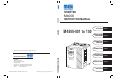
INVERTER M4000 M4000 INSTRUCTION MANUAL OUTLINE Chapter 1 INVERTER M 4500-001 to 100 INSTALLATION AND WIRING Chapter 2 OPERATION/ CONTROL Chapter 3 PARAMETERS Chapter 4 Specifications an contents are subject to change without notice. PROTECTIVE Chapter 5 FUNCTIONS MGI T ECHNOLOGIES INC. 275 West 4th Avenue Vancouver, British Columbia Canada V7N 3B1 Toll Free Tell: (877) 539-2542 (Canada & USA) Toll Free Fax: (800) 539-2542 (Canada & USA) Internet: www.mgitech.
Thank you for choosing this MGI Inverter. This instruction manual gives handling information and precautions for use of this equipment. Incorrect handling might cause an unexpected fault. Before using the inverter, please read this manual carefully to use the equipment to its optimum. Please forward this manual to the end user.
SAFETY INSTRUCTIONS 1. Electric Shock Prevention WARNING z While power is on or when the inverter is running, do not open the front cover. You may get an electric z z z z z z z z z shock. Do not run the inverter with the front cover removed. Otherwise, you may access the exposed highvoltage terminals or the charging part of the circuitry and get an electric shock. If power is off, do not remove the front cover except for wiring or periodic inspection.
. Additional instructions Also note the following points to prevent an accidental failure, injury, electric shock, etc.: (1) Transportation and installation CAUTION z When carrying products, use correct lifting gear to prevent injury. z Do not stack the inverter boxes higher than the number recommended. z Ensure that installation position and material can withstand the weight of the inverter. Install z z z z z z z according to the information in the Instruction Manual.
CAUTION z The load used should be a three-phase induction motor only. Connection of any other electrical equipment to the inverter output may damage the equipment. z The electronic over current protection does not guarantee protection of the motor from overheating. z Do not use a magnetic contactor on the inverter input for frequent starting/stopping of the inverter. z Use a noise filter to reduce the effect of electromagnetic interference.
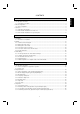
1 OUTLINE 1 1.1 Pre-Operation Information .........................................................................................................................................1 1.1.1 Precautions for operation...................................................................................................................................1 1.2 Basic Configuration..............................................................................................................................................
4 PARAMETERS 48 4.1 Parameter List .........................................................................................................................................................48 4.1.1 Parameter list...................................................................................................................................................48 4.1.2 List of Parameters Classified by Purposes of Use...........................................................................................
z Output current detection function (Pr. 150, Pr. 151)..............................................................................................130 z Zero current detection (Pr. 152, Pr. 153)...............................................................................................................131 z RT signal activated condition selection (Pr. 155) ..................................................................................................
5.3.6 Replacement of parts.....................................................................................................................................189 5.3.7 Inverter replacement ......................................................................................................................................190 5.3.8 Measurement of main circuit voltages, currents and power...........................................................................191 6 SPECIFICATIONS 193 6.
CHAPTER 1 OUTLINE This chapter gives information on the basic "outline" of this product. Always read the instructions in this chapter before using the equipment. 1.1 Pre-Operation Information........................................ 1 1.2 Basic Configuration.................................................. 2 1.3 Structure ..................................................................
1.1 Pre-Operation Information OUTLINE 1 OUTLINE 1.1 Pre-Operation Information 1.1.1 Precautions for operation Incorrect handling might cause the inverter to operate improperly, its life to be reduced considerably, or at the worst, the inverter to be damaged. Handle the inverter properly in accordance with the information in each section as well as the precautions and instructions of this manual to use it correctly. This manual is written for the M4000 series inverters.
1.2 Basic Configuration OUTLINE 1.2 Basic Configuration 1.2.1 Basic configuration The following devices are required to operate the inverter. Proper peripheral devices must be selected and correct connections made to ensure proper operation. Incorrect system configuration and connections can cause the inverter to operate improperly, its life to be reduced considerably, and in the worst case, the inverter to be damaged.
1.3 Structure OUTLINE 1.3 Structure 1.3.
OUTLINE 1.3.2 Removal and reinstallation of the front cover M4500-001 to 010 • Removal 1) Hold both sides of the front cover top and push the front cover down. 2) Hold down the front cover and pull it toward you to remove. (The front cover may be removed with the PU (FR-DU04/FR-PU04) on.) Catch Inverter 1 Front cover • Reinstallation 1) Insert the catches at the bottom of the front cover into the sockets of the inverter.
OUTLINE M4500-060 / 100 • Removal 1) Remove the front cover mounting screws. • Reinstallation 1) Fix the front cover with the mounting screws. Note: 1. Make sure that the front cover has been reinstalled securely. 2. The same serial number is printed on the capacity plate of the front cover and the rating plate of the inverter. Before reinstalling the front cover, check the serial number to ensure that the cover removed is reinstalled to the inverter from where it was removed.
OUTLINE 1.3.3 Removal and reinstallation of the operation panel To ensure safety, remove and reinstall the operation panel after switching power off. • Removal Hold down the top button of the operation panel and pull the operation panel toward you to remove. Removal Reinstallation 1 To reinstall, insert straight and mount securely. • Reinstallation using the connection cable 1) Remove the operation panel. 2) Disconnect the modular jack type relay connector.
MEMO
CHAPTER 2 INSTALLATION AND WIRING This chapter gives information on the basic "installation and wiring" of this product. Always read the instructions in this chapter before using the equipment. 2.1 Installation................................................................ 7 2.2 Wiring ...................................................................... 10 2.3 Other wiring .............................................................
2.1 Installation INSTALLATION AND WIRING 2 INSTALLATION AND WIRING 2.1 Installation 2.1.1 Instructions for installation 1) Handle the unit carefully. The inverter uses plastic parts. Handle it gently to protect it from damage. Also, hold the unit with even strength and do not apply too much strength to the front cover alone. 2 2) Install the inverter in a place where it is immune to vibration. (5.9 m/s {0.6G} or less) Also note the cart, press, etc.
INSTALLATION AND WIRING 8) For installation in an enclosure Ventilation fan Inveter Inveter Inveter Inveter Inveter Inveter Built-in cooling fan (Correct example) (Correct example) (Incorrect example) Position of Ventilation Fan (Incorrect example) Accommodation of two or more inverters 9) Vertical mounting 2 (1) Wiring cover and handling 1) When cable conduits are not connected Cut the protective bushes of the wiring cover with nippers or a cutter before running the cables.
INSTALLATION AND WIRING (2) Installation of attachment for conduit connection (060, 100) An attachment for conduit connection is a standard accessory for models M4500-060 and M4500-100. It is shipped together with the inverter in one crate. If the inverter is not installed inside an electrical enclosure, mount this attachment according to the below instructions. If the inverter is mounted inside an electrical enclosure and conduit is not used, it is not necessary to use this attachment.
2.2 Wiring INSTALLATION AND WIRING 2.2 Wiring 2.2.1 Terminal connection diagram NFB Motor R U PU connector S T 3-phase AC power supply IM V W (RS-485) Ground R1 Jumper S1 24VDC power output and external transistor common (Contact input common for source logic) P1 PC Forward rotation start STF Reverse rotation start STR Start self-holding selection Jumper Remove this jumper when using DC reactor. P R (Note) PX (Note) PR Jumper Remove this jumper when using external brake resister.
INSTALLATION AND WIRING (1) Description of main circuit terminals Symbol R, S, T U, V, W Terminal Name AC power input Inverter output Description Connect to the commercial power supply. Connect a three-phase squirrel-cage motor. Connected to the AC power supply terminals R and S. To retain the alarm display and alarm output, remove the jumpers from terminals R-R1 and S-S1 and apply external power to these terminals.
INSTALLATION AND WIRING Type Symbol Terminal Name 10E *1: *2: *3: Analog frequency setting Frequency setting (voltage) 4 Frequency setting (current) 1 Auxiliary frequency setting 5 Frequency setting input common A, B, C Alarm output Inverter running SU Up to frequency OL Overload alarm IPF Instantaneous power failure FU Frequency detection SE Open collector output common Pulse RUN For meter Analog Open collector 2 FM AM Analog signal output Common to the RUN, SU, OL, IPF a
INSTALLATION AND WIRING 2.2.2 Wiring of the main circuit (1) Wiring instructions 1) Crimping terminals with insulation sleeves are recommended for use with the power and motor cables. 2) Cut the protective bushes of the wiring cover when running the cables. 3) Power must not be applied to the output terminals (U, V, W) of the inverter. Otherwise the inverter will be damaged. 4) After wiring, wire off-cuts must not be left in the inverter. Wire off-cuts can cause an alarm, failure or malfunction.
INSTALLATION AND WIRING 8) Electromagnetic wave interference The input/output (main circuit) of the inverter includes harmonic components, which may interfere with the communication devices (such as AM radios) used near the inverter. In this case, install FR-BSF01 or FR-BLF line noise filter to minimize interference. 9) Do not install a power capacitor, surge suppressor in the output side of the inverter. This will cause the inverter to trip or the capacitor and surge suppressor to be damaged.
INSTALLATION AND WIRING (2) Terminal block layout In the main circuit of the inverter, the terminals are arranged as shown below: M4500-001 to 010 M4500-060, 100 R1 S1 R Screw size (M4) Charge lamp S Charge lamp R S T U V N P1 P PR PX screw size (M5) R S Screw size (M8) Jumpers T U V V W S N Screw size (M4) P1 P Screw size (M4) Charge lamp S U S1 R W M4500-025, 040 R T R1 W N R1 S1 R S P1 P Screw size (M4) Screw size (M6) Jumper Screw size (M6) Note: 010
INSTALLATION AND WIRING (3) Cables, crimping terminals, etc.
INSTALLATION AND WIRING (5) Connecting the control circuit to a power supply separately from the main circuit If the magnetic contactor (MC) in the inverter power supply is opened when the protective circuit is operated, the inverter control circuit power is lost and the alarm output signal cannot be kept on. To keep the alarm signal on terminals R1 and S1 are available. In this case, connect the power supply terminals R1 and S1 of the control circuit to the primary side of the MC.
INSTALLATION AND WIRING 2.2.3 Wiring of the control circuit (1) Wiring instructions 1) Terminals SD, SE and 5 are common to the I/O signals and isolated from each other. These common terminals must not be connected to each other or earthed. 2) Use shielded or twisted cables for connection to the control circuit terminals and run them away from the main and power circuits (including the 200V relay sequence circuit). 3) The frequency input signals to the control circuit are micro currents.
INSTALLATION AND WIRING (3) Changing the control logic The input signal logic is factory-set to the sink mode. To change the control logic, the connector on the back of the control circuit terminal block must be moved to the other position. (The output signals may be used in either the sink or source logic independently of the connector position.) 1) Loosen the two mounting screws in both ends of the control circuit terminal block. (The screws cannot be removed.
INSTALLATION AND WIRING 4) Sink logic type • In this logic, a signal switches on when a current flows out of the corresponding signal input terminal. Terminal SD is common to the contact input signals. Terminal SE is common to the open collector output signals. A current flows out of the corresponding signal RUN R Current STF RUN R STR SD SE • When using an external power supply for transistor output, use terminal PC as a common to prevent misoperation caused by leakage current.
INSTALLATION AND WIRING 5) Source logic type • In this logic, a signal switches on when a current flows into the corresponding signal input terminal. Terminal PC is common to the contact input signals. Terminal SE is common to the open collector output signals. A current flows out of the corresponding signal RUN PC Current STF RUN R STR R SE • When using an external power supply for transistor output, use terminal SD as a common to prevent misoperation caused by leakage current.
INSTALLATION AND WIRING 2.2.4 Connection to the PU connector (1) When connecting the operation panel or parameter unit using a connection cable • Parameter unit connection cable (FR-CB2) (option) or the following connector and cable. • Connector: RJ45 connector Example: 5-554720-3, Nippon AMP • Cable: Cable conforming to EIA568 (e.g. 10BASE-T cable) Example: SGLPEV 0.5mm×4P, MITSUBISHI CABLE INDUSTRIES, LTD. Note: The maximum wiring length is 20m (65.62 feet).
INSTALLATION AND WIRING 2) When a computer having a RS-232C interface is used with inverters Computer RS-232C connector RS-232C cable Max. 15m *Converter Station 1 Station 2 Station n Inverter Inverter Inverter PU connector (Note 1) PU connector (Note 1) PU connector (Note 1) RS-485 terminal Terminal resistor Distribution terminal 10BASE-T cable (Note 2) *Converter available on the market is required. (Note 3) Use the connector, cables and converter, which are available on the market.
INSTALLATION AND WIRING 2.2.5 Connection of brake resistor and DC reactor Incorrect connection will cause inverter damage or accident. (1) Connection of the external brake resistor (010 or less) The built-in brake resistor is connected across terminals P and PR. Fit the external brake resistor instead when the built-in brake resistor does not have enough thermal capability for high-duty operation. Remove the jumper from across terminals PR-PX and connect the external brake resistor across terminals P-PR.
INSTALLATION AND WIRING (2) Connection of the power factor improving DC reactor Connect the power factor improving DC reactor between terminals P1-P. In this case, the jumper P1 connected across terminals P1-P must be removed. Otherwise, the reactor will not function. Remove P the jumper. Note: 1. The wiring distance should be within 5m. 2. The size of the cables used should be equal to or larger than that of the power supply cables (R, S, T).
INSTALLATION AND WIRING 2.2.6 Design information 1) For commercial power supply-inverter switch-over operation, provide electrical and mechanical interlocks for MC1 and MC2 designed for commercial power supply-inverter switch-over. When there is a commercial power supply-inverter switch-over circuit as shown below, the inverter will be damaged by leakage current from the power supply due to arcs generated at the time of switch-over or chattering caused by a sequence error.
2.3 Other wring INSTALLATION AND WIRING 2.3 Other wiring 2.3.1 Inverter-generated noises and reduction techniques Some noises enter the inverter causing it to misoperate and others are radiated by the inverter causing misoperation of peripheral devices. Though the inverter is designed to be insusceptible to noise, it handles low-level signals, so it requires the following basic measures to be taken. Also, since the inverter chops the output at a high carrier frequency, it could generate noise.
INSTALLATION AND WIRING 5) Telephone 7) 7) 2) 1) Instrument Receiver 2) Sensor power supply In3) verter 6) 4) Motor Noise Path 1) 2) 3) 4) 5) 6) 7) 8) IM 8) 3) Sensor Measures When devices which handle low-level signals and are susceptible to misoperation due to noise (such as instruments, receivers and sensors) are installed near the inverter and their signal cables are contained in the same panel as the inverter or are run near the inverter, the devices may be effected by air-propagated no
INSTALLATION AND WIRING z Data line filter Noise entry can be prevented by providing a data line filter for the detector cable etc. z Example of measures against noises Control box Reduce carrier frequency. Install filter (FR-BLF,FRBSF01) to inverter input side. Install filter (FR-BLF,FR-BSF01) to inverter output side. FRBLF Inverter power supply Inverter FRBLF Motor Install capactor type filter to inverter input side. Use 4-core cable for motor power cable and use one cable as ground cable.
INSTALLATION AND WIRING 2.3.2 Leakage currents and countermeasures Due to the static capacitance existing in the inverter I/O wiring and motor, leakage currents flow through them. Since their values depend on the static capacitance, carrier frequency, etc., take the following measures. (1) To-ground leakage currents Leakage currents may flow not only into the inverter's own line but also into the other line through the ground cable, etc.
INSTALLATION AND WIRING 2.3.3 Inverter-driven 575V class motor Voltage at a motor terminal (%) In the PWM type inverter, a surge voltage attributable to wiring constants is generated at the motor terminals. Especially for a 575V class motor, the surge voltage may deteriorate the insulation.
INSTALLATION AND WIRING 2.3.4 Peripheral devices (1) Selection of peripheral devices Check the capacity of the motor to be used with the inverter you purchased. Appropriate peripheral devices must be selected according to the capacity. Refer to the following list and prepare appropriate peripheral devices: Inverter Type M4500-001 M4500-003 M4500-005 M4500-010 M4500-010 M4500-025 M4500-025 M4500-040 M4500-040 M4500-060 M4500-060 M4500-100 Motor Output (kW (HP)) 0.75 (1) 2.2 (3) 3.7 (5) 5.5 (7.5) 7.
INSTALLATION AND WIRING (2) Selection the rated sensitivity current for the earth leakage circuit breaker Leakage current (mA) Leakage current (mA) When using the earth leakage circuit breaker with the inverter circuit, select its rated sensitivity current as follows, independent of the carrier frequency setting: Rated sensitivity current: Example of leakage current Leakage current example per 1kW for commercial of 3-phase induction motor l∆n ≥ 10 × {lg1 + lgn + 3 × (lg2+lgm)} power supply operation when
INSTALLATION AND WIRING 2.3.5 Additional guidelines for compliance with UL and CSA standards (Since we obtained the approval of the UL and CSA standards from the UL, the products conforming to the standards carry the US, Canada UL mark.) (1) Wiring of the power supply and motor Use UL Recognized round crimping terminals to wire the input (R, S, T) and output (U, V, W) terminals of the inverter. Crimp the terminals with a crimping tool recommended by the terminal manufacturer.
MEMO
CHAPTER CHAPTER33 OPERATION/CONTROL OPERATION/CONTROL This chapter provides the basic "operation" for use of this product. Always read this chapter before using the equipment. 3.1 Pre-Operation Information........................................ 35 3.2 Operation Panel ....................................................... 38 3.3 Operation .................................................................
3.1 Pre-Operation information OPERATION/CONTROL 3 OPERATION/CONTROL 3.1 Pre-Operation Information 3.1.1 Devices and parts to be prepared for operation The inverter can be operated in any of the "external operation mode", "PU operation mode", "combined operation mode" and "communication operation mode". Prepare required instruments and parts according to the operation mode.
OPERATION/CONTROL Preparation · Start signal ..................................Switch, relay, etc. (for 1) · Frequency setting signal .............0 to 5V, 0 to 10V or 4 to 20mA DC signals from a potentiometer or outside the inverter (for 2) · Operation unit..............................Operation panel (FR-DU04), parameter unit (FR-PU04) · Connection cable ........................
OPERATION/CONTROL 3.1.2 Power on Before switching power on, check the following: • Installation check Make sure that the inverter is installed correctly in a correct place. (Refer to page 7.) Wiring check Make sure that the main and control circuits are wired correctly. Make sure that the options and peripheral devices are selected and connected correctly. (Refer to page 10.) · • Switch power on.
3.2 Operation Panel OPERATION/CONTROL 3.2 Operation Panel With the operation panel (FR-DU04), you can set the running frequency, monitor the operation command display, set parameters, display an error, and copy parameters. 3.2.
OPERATION/CONTROL 3.2.
OPERATION/CONTROL 3.2.5 Parameter setting mode · A parameter value may either be set by updating its parameter number or setting the value digit-by-digit · using the [UP/DOWN] key. To write the setting, change it and press the [SET] key 1.5 seconds. Set "1" (PU operation mode) in Pr. 79 "operation mode selection" or select the PU operation mode.
OPERATION/CONTROL 3.2.7 Help mode FR-DU04 zAlarm history zAlarm history clear CONTROL PANEL zParameter clear zAll clear zUser clear zSoftware version read Hz A V MON EXT PU REV FWD SET To 1) Monitoring mode (1) Alarm history Four past alarms can be displayed with the [UP/DOWN] key. ("." is appended to the most recent alarm.) (When no alarm exists, E. 0 is displayed.
OPERATION/CONTROL (3) Parameter clear Initialises the parameter values to the factory settings. The calibration values are not initialized. (Parameter values are not cleared by setting "1" in Pr. 77 "parameter write disable selection).) Flicker FR-DU04 Hz A V MON FR-DU04 CONTROL PANEL EXT PU REV FWD FR-DU04 CONTROL PANEL MON SET EXT PU REV FWD FR-DU04 CONTROL PANEL Hz A V SET Hz A V MON EXT PU REV FWD CONTROL PANEL Hz A V SET 1.5 sec.
OPERATION/CONTROL 3.2.8 Copy mode By using the operation panel (FR-DU04), the parameter values can be copied to another inverter (only the M4000 series up to 100). 1) Operation procedure After reading the parameter values from the copy source inverter, connect the operation panel to the copy destination inverter, and write the parameter values. After writing the parameters to the inverter of copy destination, always reset the inverter, e.g. switch power off once, before starting operation.
3.3 Operation OPERATION/CONTROL 3.3 Operation 3.3.1 Pre-operation checks Before starting operation, check the following: • Safety Perform test operation after making sure that safety is ensured if the machine should become out of control. • Machine Make sure that the machine is free of damage. • Parameters Set the parameter values to match the operating machine system environment. • Test operation Perform test operation and make sure that the machine operates safely under light load at a low frequency.
OPERATION/CONTROL 3.3.2 External operation mode (Operation using external input signals) (1) Operation at 60Hz Step 1 Description Power-on → Operation mode check Switch power on and make sure that the operation command indication "EXT" is lit. (If it is not lit, switch to the external operation mode. For operation mode changing, refer to page 40.) Start Turn on the start switch (STF or STR). The operation status indication "FWD" or "REV" flickers.
OPERATION/CONTROL 3.3.3 PU operation mode (Operation using the operation panel (FR-DU04)) (1) Operation at 60Hz While the motor is running, repeat the following steps 2 and 3 to vary the speed: Step 1 2 3 Description Power-on → Operation mode check Switch power on and make sure that the operation command indication "PU" is lit. (If it is not lit, switch to the PU operation mode. For operation mode changing, refer to page 40.
OPERATION/CONTROL 3.3.4 Combined operation mode (Operation using the external input signals and PU) When entering the start signal from outside the inverter and setting the running frequency from the PU (Pr. 79 = 3) The external frequency setting signals and the PU's FWD, REV and STOP keys are not accepted. (Note) Step Description Image Power-on Switch power on. ON 1 2 Operation mode selection Set "3" in Pr. 79 "operation mode selection".
CHAPTER 4 PARAMETERS This chapter explains the "parameters" of this product. With the factory settings, the inverter is designed to perform simple variable-speed operation. Set necessary parameter values according to the load and operating specifications. Always read the instructions before using the equipment. 4.1 Parameter List ......................................................... 48 4.2 Parameter Function Details......................................
4.1 Parameter List PARAMETERS 4 PARAMETERS 4.
Operation selection functions Additional function Automatic restart functions Display functions Function Parameter Number Advanced magnetic flux vectorcontrol Setting Range Minimum Setting Increments Factory Setting Refer To Page: 1 0 76 1 1 76 0 to 20, 22, 23, 24, 25, 100 0 to 3, 5 to 14, 17, 18 1 to 3, 5 to 14, 17, 18, 21 0 to 400Hz 1 1 76 0.01Hz 78 0 to 500A 0.01A 60Hz Rated output current Restart coasting time 0, 0.1 to 5 s, 9999 0.
Third functions 5-point flexible V/F characteristics Function Parameter Number Communication functions PID control Commercial power supplyinverter switch-over Setting Range Minimum Setting Increments Factory Setting Refer To Page: V/F4 (fourth frequency voltage) (Note 1) 0 to 1000V 0.1V 0 108 108 V/F5 (fifth frequency) (Note 1) 0 to 400Hz, 9999 0.01Hz 9999 108 109 V/F5 (fifth frequency voltage) (Note 1) 0 to 1000V 0.
Minimum Setting Increments Factory Setting Refer To Page: Stall prevention level at 0V input 0 to 200% 0.1% 150% 67 149 Stall prevention level at 10V input 0 to 200% 0.1% 200% 67 150 Output current detection level 0 to 200% 0.1% 150% 130 151 Output current detection period 0 to 10 s 0.1 s 0 130 152 Zero current detection level 0 to 200.0% 0.1% 5.0% 131 153 0 to 1 s 0.01 s 0.
Parameter Number Additional function 199 User's initial value setting 200 Programmed operation minute/ second selection 201 Program set 1 1 to 10 Additional function Stop selection Sub functions Multi-speed operation function Programmed operation Function Selection Power failure stop function function Parameter List PARAMETERS 211 Name Program set 2 11 to 20 221 Program set 3 21 to 30 231 232 233 234 235 236 237 238 239 Timer setting Multi-speed setting (speed 8) Multi-speed setting (sp
Additional function Calibration functions Brake sequence functions Stop on contact High-speed frequency control Function Parameter Number Name Setting Range Minimum Setting Increments Factory Setting Refer To Page: 271 High-speed setting maximum current 0 to 200% 0.1% 50% 152 272 Mid-speed setting minimum current 0 to 200% 0.1% 100% 152 273 Current averaging range 0 to 400Hz, 9999 0.
PARAMETERS 4.1.2 List of Parameters Classified by Purposes of Use Set the parameters according to the operating conditions. The following list indicates purposes of use and parameters. (For full information on the parameters, Refer to Chapter 4.
PARAMETERS 4.1.3 Parameter recommended to be set by the user We recommend the following parameters to be set by the user. Set them according to the operation specifications, load, etc.
4.2 Parameter Function Details PARAMETERS 4.2Torque Parameter Function Details z boost (Pr. 0, Pr. 46, Pr. 112) Related parameters Pr. 0 "torque boost" Pr. 3 "base frequency" Pr. 19 "base frequency voltage" Pr. 71 "applied motor" Pr. 80 "motor capacity" Pr. 81 "number of motor poles" Pr. 180 to Pr. 186 (input terminal function selection) Pr. 46 "second torque boost" Pr.
PARAMETERS z Output frequency range (Pr. 1, Pr. 2, Pr. 18) Pr. 1 "maximum frequency" Related parameters Pr.13 "starting frequency" Pr. 903 "frequency setting voltage gain" Pr. 905 "frequency setting current gain" Pr. 2 "minimum frequency" Pr. 18 "high-speed maximum frequency" Used to clamp the upper and lower limits of the output frequency. Used for high-speed operation at or over 120Hz. z Can be used to set the upper and lower limits of motor speed.
PARAMETERS z Base frequency, base frequency voltage (Pr. 3, Pr. 19, Pr. 47, Pr. 113) Related parameters Pr. 3 "base frequency" Pr. 19 "base frequency voltage" Pr. 47 "second V/F (base frequency) Pr. 113 "third V/F (base frequency) Pr. 71 "applied motor" Pr. 80 "motor capacity" Pr. 81 "number of motor poles" Pr. 83 "rated motor voltage" Pr. 84 "rated motor frequency" Pr. 180 to Pr. 186 (input terminal function selection) Used to adjust the inverter outputs (voltage, frequency) to the motor rating.
PARAMETERS z Multi-speed operation (Pr. 4 to Pr. 6, Pr. 24 to Pr. 27, Pr. 232 to Pr. 239) Related parameters Pr. 4 "3-speed setting (high speed)" Pr. 1 "maximum frequency" Pr. 2 "minimum frequency" Pr. 15 "jog frequency" Pr. 28 "multi-speed input compensation" Pr. 29 "acceleration/deceleration pattern" Pr. 79 "operation mode selection" Pr. 180 to Pr. 186 (input terminal function selection) Pr. 5 "3-speed setting (middle speed)" Pr. 6 "3-speed setting (low speed)" Pr. 24 to Pr.
PARAMETERS z Acceleration/deceleration time (Pr. 7, Pr. 8, Pr. 20, Pr. 21, Pr. 44, Pr. 45, Pr. 110, Pr. 111) Pr. 7 "acceleration time" Related parameters Pr. 8 "deceleration time" Pr. 20 "acceleration/deceleration reference frequency" Pr. 21 "acceleration/deceleration time increments" Pr. 3 "base frequency" Pr. 29 "acceleration/deceleration pattern" Pr. 180 to Pr. 186 (input terminal function selection) Pr. 44 "second acceleration/deceleration time" Pr. 45 "second deceleration time" Pr.
PARAMETERS Note: 1. In S-shaped acceleration/deceleration pattern A (refer to page 69), the set time is a period required to reach the base frequency set in Pr. 3. Acceleration/deceleration time calculation expression when the set frequency is the base frequency or higher 4 T 5 2 t = 9 × (Pr.
PARAMETERS z DC dynamic brake (Pr. 10, Pr. 11, Pr. 12) Related parameters Pr. 10 "DC dynamic brake operation frequency" Pr. 13 "starting frequency" Pr. 71 "applied motor" Pr. 11 "DC dynamic brake operation time" Pr. 12 "DC dynamic brake voltage" By setting the stopping DC dynamic brake voltage (torque), operation time and operation starting frequency, the stopping accuracy of positioning operation, etc. or the timing of operating the DC dynamic brake to stop the motor is adjusted according to the load.
PARAMETERS z Starting frequency (Pr. 13) Pr. 13 "starting frequency" Related parameters Pr. 2 "minimum frequency" You can set the starting frequency between 0 and 60Hz. z Set the starting frequency at which the start signal is switched on. Parameter Number 13 Factory Setting 0.5Hz Setting Range 0.01 to 60Hz Output frequency (Hz) Setting range 60 Pr.
PARAMETERS z Load pattern selection (Pr. 14) Related parameters Pr. 14 "load pattern selection" Pr. 0 "torque boost" Pr. 80 "motor capacity" Pr. 81 "number of motor poles" Pr. 180 to Pr. 186 (input terminal function selection) You can select the optimum output characteristic (V/F characteristic) for the application and load characteristics. Factory Setting 0 Pr.14=0 Setting Range 0 to 5 Pr.14=1 For constant-torque loads (e.g.
PARAMETERS z Jog operation (Pr. 15, Pr. 16) Pr. 15 "jog frequency" Related parameters Pr. 20 "acceleration/deceleration reference frequency" Pr. 21 "acceleration/deceleration time increments" Pr. 79 "operation mode selection" Pr. 180 to Pr. 186 (input terminal function selection) Pr. 16 "jog acceleration/deceleration time" For jog operation in the external operation mode, choose the jog operation function using input terminal function selection, and turn the JOG signal on.
PARAMETERS z MRS input selection (Pr. 17) Pr. 17 "MRS input selection" Used to select the logic of the MRS signal. When the MRS signal switches on, the inverter shuts off the output. Parameter Number 17 Factory Setting 0 Setting Range 0, 2 Pr.
PARAMETERS z Stall prevention (Pr. 22, Pr. 23, Pr. 66, Pr. 148, Pr. 149, Pr. 154) Pr. 22 "stall prevention operation level" Related parameters Pr. 23 "stall prevention operation level at double speed" Pr. 48 "second stall prevention operation current" Pr. 49 "second stall prevention operation frequency" Pr. 73 "0-5V/0-10V selection" Pr. 114 "third stall prevention operation current" Pr. 115 "third stall prevention operation frequency" Pr. 156 "stall prevention operation selection" Pr.
PARAMETERS · In Pr. 22, set the stall prevention operation level. Normally set it to 150% (factory setting). Set "0" in Pr. 22 · to disable the stall prevention operation. To reduce the stall prevention operation level in the high-frequency range, set the reduction starting frequency in Pr. 66 and the reduction ratio compensation factor in Pr. 23. Calculation expression for stall prevention operation level Pr.22-A Pr.23-100 Stall prevention operation level (%) = A + B × [ Pr.
PARAMETERS z Acceleration/deceleration pattern (Pr. 29, Pr. 140 to Pr. 143) Pr. 29 "acceleration/deceleration pattern" Related parameters Pr. 3 "base frequency" Pr. 7 "acceleration time" Pr. 8 "deceleration time" Pr. 20 "acceleration/deceleration reference frequency" Pr. 44 "second acceleration/ deceleration time" Pr. 45 "second deceleration time" Pr. 110 "third acceleration/ deceleration time" Pr. 111 "third deceleration time" Pr. 140 "backlash acceleration stopping frequency" Pr.
PARAMETERS z Regenerative brake duty (Pr. 30, Pr. 70) Pr. 30 "regenerative function selection" Related parameters Pr. 70 "special regenerative brake duty" Pr. 180 "RL terminal function selection" Pr. 181 "RM terminal function selection" Pr. 182 "RH terminal function selection" Pr. 183 "RT terminal function selection" Pr. 184 "AU terminal function selection" Pr. 185 "JOG terminal function selection" Pr.
PARAMETERS z Frequency jump (Pr. 31 to Pr. 36) Pr. 31 "frequency jump 1A" Pr. 32 "frequency jump 1B" Pr. 33 "frequency jump 2A" Pr. 34 "frequency jump 2B" Pr. 35 "frequency jump 3A" Pr. 36 "frequency jump 3B" z When it is desired to avoid resonance attributable to the natural frequency of a mechanical system, these parameters allow resonant frequencies to be jumped. Up to three areas may be set, with the jump frequencies set to either the top or bottom point of each area.
PARAMETERS z Speed display (Pr. 37, Pr. 144) Pr. 37 "speed display" Related parameters Pr. 52 "PU main display data selection" Pr. 53 "PU level display data selection" Pr. 80 "motor capacity" Pr. 81 "number of motor poles" Pr.
PARAMETERS z Up-to-frequency sensitivity (Pr. 41) Related parameters Pr. 41 "up-to-frequency sensitivity" Pr. 190 "RUN terminal function selection" Pr. 191 "SU terminal function selection" Pr. 192 "IPF terminal function selection" Pr. 193 "OL terminal function selection" Pr. 194 "FU terminal function selection" Pr.
PARAMETERS Refer to the figure below and set the corresponding parameters: When Pr. 43 ≠ 9999, the Pr. 42 setting applies to forward rotation and the Pr. 43 setting applies to reverse rotation. · Pr.42 Output frequency Forward rotation Pr.50 Pr.116 Time Pr.43 Reverse rotation Pr.50 Pr.116 Output signal OFF FU,FU2,FU3 ON OFF ON OFF Output Signal Parameter Number 42 43 50 116 Output Signal FU FU2 FU3 Use Pr. 190 to Pr. 195 to assign the terminals used to output the FU2 and FU3 signals.
PARAMETERS · Set the stall prevention operation level in Pr. 48 and Pr. 114. · Refer to the following list to set values in Pr. 49 and Pr. 115. · Pr. 114 and Pr. 115 are made valid by switching on the X9 signal. Set "9" in any of Pr. 180 to Pr. 186 to allocate the terminal used to input the X9 signal. Pr. 49 Setting Pr. 115 Setting 0 0.01Hz to 400Hz 9999 Cannot be set. Operation Second (third) stall prevention function is not activated.
PARAMETERS z Monitor display/FM, AM terminal function selection (Pr. 52 to Pr. 54, Pr. 158) Pr. 52 "DU/PU main display screen data selection" Pr. 53 "PU level display data selection" Related parameters Pr. 37 "speed display" Pr. 55 "frequency monitoring reference" Pr. 56 "current monitoring reference" Pr. 170 "watt-hour meter clear" Pr. 171 "actual operation hour meter clear" Pr. 900 "FM terminal calibration" Pr. 901 "AM terminal calibration" Pr. 54 "FM terminal function selection" Pr.
PARAMETERS When 100 is set in Pr. 52, the monitored values during stop and during operation differ as indicated below: (The LED on the left of Hz flickers during a stop and is lit during running.) Pr. 52 Output frequency Output current Output voltage Alarm display 0 During operation/during stop Output frequency 100 During stop During operation Set frequency Output current Output voltage Alarm display Output frequency Note: 1. During an error, the output frequency at error occurrence is displayed. 2.
PARAMETERS z Monitoring reference (Pr. 55, Pr. 56) Pr. 55 "frequency monitoring reference" Related parameters Pr. 56 "current monitoring reference" Pr. 37 "speed display" Pr. 53 "PU level display data selection" Pr. 54 "FM terminal function selection" Pr. 158 "AM terminal function selection" Pr. 900 "FM terminal calibration" Pr.
PARAMETERS z Automatic restart after instantaneous power failure (Pr. 57, Pr. 58, Pr. 162 to Pr. 165) Pr. 57 "coasting time for automatic restart after instantaneous power failure/commercial power supply-inverter switch-over" Pr. 58 "cushion time for automatic restart after instantaneous power failure/commercial power supply-inverter switch-over" Pr.162 "Automatic restart after instantaneous power failure selection" Pr.163 "First cushion time for restart" Pr.164 "First cushion voltage for restart" Pr.
PARAMETERS Refer to the above figures and following table, and set the parameters: Parameter Number Setting 0 162 1 0 57 Frequency search made Frequency search is made after detection of an instantaneous power failure. No frequency search Independently of the motor coasting speed, the output voltage is gradually increased with the frequency kept as preset. 001 0.5 s coasting time 003 to 010 1.0 s coasting time 025 or more 3.0 s coasting time 0.
PARAMETERS z Remote setting function selection (Pr. 59) Related parameters Pr. 59 "remote setting function selection" Pr. 1 "maximum frequency" Pr. 7 "acceleration time" Pr. 8 "deceleration time" Pr. 18 "high-speed maximum frequency" Pr. 28 "multi-speed input compensation" Pr. 44 "second acceleration/deceleration time" Pr.
PARAMETERS CAUTION When selecting this function, re-set the maximum frequency according to the machine. z Intelligent mode selection (Pr. 60) Related parameters Pr. 60 "intelligent mode selection" Pr. 0 "torque boost" Pr. 7 "acceleration time" Pr. 8 "deceleration time" Pr. 13 "starting frequency" Pr. 19 "base frequency voltage" Pr. 80, Pr. 81 (advanced magnetic flux vector control) Pr. 278 to Pr. 285 (brake sequence functions) The inverter automatically sets appropriate parameters for operation.
PARAMETERS Pr. 60 Setting Operation Mode Description Automatically Set Parameters 0 Ordinary operation mode 1, 2 Shortest acceleration/ deceleration mode 3 Optimum acceleration/ deceleration mode (Note 2, 4) 4 Energy-saving mode (Note 3, 5) 5, 6 Elevator mode (Note 3) 7 Brake sequence mode 8 Set to accelerate/decelerate the motor in the shortest time. The inverter makes acceleration/deceleration in the shortest time using its full capabilities.
PARAMETERS z Acceleration/deceleration reference current/lift mode starting frequency (Pr. 61 to Pr. 64) Pr. 61 "reference current" Related parameter Pr. 62 "reference current for acceleration" Pr. 60 "intelligent mode selection" Pr. 63 "reference current for deceleration" Pr. 64 "starting frequency for elevator mode" z Set these parameters to improve performance in the intelligent mode.
PARAMETERS z Retry function (Pr. 65, Pr. 67 to Pr. 69) Pr. 65 "retry selection" Pr. 67 "number of retries at alarm occurrence" Pr. 68 "retry waiting time" Pr. 69 "retry count display erasure" When an alarm occurs, the retry function causes the inverter to automatically reset itself to make a restart and continue operation. You can select whether retry is made or not, alarms reset for retry, number of retries made, and waiting time.
PARAMETERS · Use Pr. 67 to set the number of retries at alarm occurrence. Pr. 67 Setting 0 1 to 10 101 to 110 · · Number of Retries Retry is not made. 1 to 10 times 1 to 10 times Alarm Signal Output Not output. Output. Use Pr. 68 to set the waiting time from when an inverter alarm occurs until a restart in the range 0 to 10 seconds. Reading the Pr. 69 value provides the cumulative number of successful restart times made by retry. The setting of "0" erases the cumulative number of times. Note: 1.
PARAMETERS z Applied motor (Pr. 71) Pr. 71 "applied motor" Related parameters Pr. 0 "torque boost" Pr. 12 "DC dynamic brake voltage" Pr. 19 "base frequency voltage" Pr. 60 "intelligent mode" Pr. 80 "motor capacity" Pr. 81 "number of motor poles" Pr. 96 "auto tuning setting/status" Pr. 100 to Pr. 109 "V/F frequency/voltage" Set the motor used.
PARAMETERS z PWM carrier frequency (Pr. 72, Pr. 240) Pr. 72 "PWM frequency selection" Pr. 240 "Soft-PWM setting" You can change the motor tone. z By parameter setting, you can select Soft-PWM control which changes the motor tone. z Soft-PWM control changes motor noise from a metallic tone into an unoffending complex tone. Parameter Number 72 240 Factory Setting 2 1 Setting Range 0 to 15 0, 1 Remarks 0: 0.7kHz, 15: 14.
PARAMETERS z Voltage input (Pr. 73) Pr. 73 "0-5V/0-10V selection" Related parameters Pr. 22 "stall prevention operation level" Pr. 903 "frequency setting voltage bias" Pr. 905 "frequency setting current gain" You can select the analog input terminal specifications, the override function and the function to switch between forward and reverse rotation depending on the input signal polarity. Parameter Number 73 Factory Setting 1 Setting Range 0 to 5, 10 to 15 Pr.
PARAMETERS z Input filter time constant (Pr. 74) Pr. 74 "filter time constant" You can set the input section's internal filter constant of an external voltage or current frequency setting signal. z Effective for eliminating noise in the frequency setting circuit. z Increase the filter time constant if steady operation cannot be performed due to noise. A larger setting results in lower response. (The time constant can be set between approximately 1ms to 1s. with the setting of 0 to 8.
PARAMETERS How to make a restart after a stop made by the [STOP] key from the PU during external operation (1) Operation panel (FR-DU04) 1) After completion of deceleration to a stop, switch off the STF or STR signal. 2) Press the [MODE] key two times* to call the indication. (Note 8) Note: When Pr. 79 = "3", press the [MODE] key three times, to display and proceed to step 3). , then press the [DOWN] key (* For monitor screen) .....................
PARAMETERS CAUTION Do not reset the inverter with the start signal on. Otherwise, the motor will start instantly after resetting, which may lead to hazardous conditions. z Alarm code output selection (Pr. 76) Related parameters Pr. 76 "alarm code output selection" Pr. 79 "operation mode selection" Pr. 190 to Pr. 195 (multi-function outputs) Pr. 200 to Pr. 231 "programmed operation" When an alarm occurs, its code can be output as a 4-bit digital signal from the open collector output terminals.
PARAMETERS z Parameter write inhibit selection (Pr. 77) Pr. 77 "parameter write disable selection" Related parameters Pr. 79 "operation mode selection" You can select between write-enable and disable for parameters. This function is used to prevent parameter values from being rewritten by accident. Parameter Number 77 Factory Setting 0 Setting Range 0, 1, 2 Pr. 77 Setting 0 1 2 Function Write enabled during a stop only.
PARAMETERS z Reverse rotation prevention selection (Pr. 78) Pr. 78 "reverse rotation prevention selection" Related parameters Pr. 79 "operation mode selection" This function can prevent any reverse rotation fault resulting from the misoperation of the start signal. z Used for a machine which runs only in one direction, e.g. fan, pump. (The setting of this function is valid for the PU, external and communication operations.) Parameter Number 78 Factory Setting 0 Setting Range 0, 1, 2 Pr.
PARAMETERS z Operation mode selection (Pr. 79) Pr. 79 "operation mode selection" Related parameters Pr.Pr.1515"jog "jogfrequency" frequency" Pr.Pr.4 4totoPr. 27, Pr.232 Pr.232totoPr.239 Pr.239 Pr.6,6,Pr. Pr. 24 24 to to 27, (multi-speed operation) "multi-speed operation" Pr.Pr.7676"alarm selection" "alarmcode code output output selection" Pr.Pr.180 to Pr. 186 180 to Pr. 186 (input (inputterminal terminalfunction function selection) selection) Pr.Pr.200 to Pr. 231 200 to Pr.
PARAMETERS (2) Switch-over mode You can select between PU operation, external operation and computer link operation (when FR-A5NR option is used). Operation Mode Switching External operation to PU operation External operation to computer link operation PU operation to external operation PU operation to computer link operation Computer link operation to external operation Computer link operation to PU operation Switching Operation/Operating Status 1) Select the PU operation mode.
PARAMETERS Operating Condition Operation mode PU Status During stop ON → OFF (Note 3) During operation ON → OFF (Note 3) During stop External X12 (MRS) Signal During operation OFF → ON ON → OFF OFF → ON ON → OFF Operation Mode (Note 4) External Operating Status Parameter Write Switching to PU Operation Mode During stop Allowed → disallowed Disallowed If external operation frequency setting and start signal are entered, o
PARAMETERS z Motor capacity/number of motor poles/speed control gain (Pr. 80, Pr. 81, Pr. 89) Pr. 80 "motor capacity" Related parameters Pr. 81 "number of motor poles" Pr. 89 "speed control gain" You can set the advanced magnetic flux vector control. z Advanced magnetic flux vector control Provides large starting torque and sufficient low-speed torque. Effective for great load fluctuation. Parameter Number 80 81 89 Factory Setting 9999 9999 100% Pr. 71 "applied motor" Pr. 83 "rated motor voltage" Pr.
PARAMETERS (1) Advanced magnetic flux vector control · By setting the capacity, number of poles and type of the motor used in Pr. 80 and Pr. 81, the advanced magnetic flux vector control can be selected. Parameter Number 80 Setting Description 9999 0.4 to 55 9999 2, 4, 6 V/F control Set the motor capacity applied. V/F control Set the number of motor poles. V/F control is selected when the X18 (magnetic flux-V/F switch-over) signal switches on. (This selection is not made during operation.
PARAMETERS z Offline auto tuning function (Pr. 82 to Pr. 84, Pr. 90 to Pr. 94, Pr. 96) Pr. 82 "motor exciting current" Related parameters Pr. 83 "rated motor voltage" Pr. 7 "acceleration time" Pr. 9 "electronic overcurrent protection" Pr. 71 "applied motor" Pr. 80 "motor capacity" Pr. 81 "number of motor poles" Pr. 95 "online auto tuning selection" Pr. 156 "stall prevention operation selection" Pr. 84 "rated motor frequency" Pr. 90 "motor constant (R1)" Pr. 91 "motor constant (R2)" Pr.
PARAMETERS Parameter Number 82 83 84 90 91 92 93 94 96 Factory Setting 9999 575V 60Hz 9999 9999 9999 9999 9999 0 Setting Range Remarks 0 to , 9999 0 to 1000V 50 to 120Hz 0 to , 9999 0 to , 9999 0 to , 9999 0 to , 9999 0 to , 9999 0, 1, 101 9999: standard motor Rated motor voltage Rated motor frequency 9999: standard motor 9999: standard motor 9999: standard motor 9999: standard motor 9999: standard motor 0: No tuning · The motor is connected.
PARAMETERS Parameter details Parameter Number 9 Setting Description 0 to 500A Set the rated motor current (A).
PARAMETERS (3) Monitoring the offline tuning status When the parameter unit (FR-PU04) is used, the Pr. 96 value is displayed during tuning on the main monitor as shown below. When the operation panel (FR-DU04) is used, only the same numerical value as on the PU is displayed: · Parameter unit (FR-PU04) main monitor (For inverter trip) 2. Tuning in progress 1. Setting TUNE 1 STOP PU TUNE 3 COMPLETION STF STOP PU PU TUNE 103 COMPLETION STF STOP PU 2 STF FWD PU 3.
PARAMETERS 5) When tuning was forced to end A forced end occurs when tuning is forced to end by pressing the [STOP] key or turning off the start signal (STF or STR) during tuning. In this case, offline auto tuning was not brought to a normal end. (The motor constants are not yet set.) Reset the inverter and restart tuning. Note: 1. The motor constants measured once in the offline auto tuning are stored as parameters and their data is held until the offline auto tuning is performed again. 2.
PARAMETERS Note: 1. Pr. 90 to Pr. 94 values may only be read when the Pr. 80 and Pr. 81 settings are other than "9999" (advanced magnetic flux vector control selected). 2. Set "9999" in Pr. 90 to Pr. 94 to use the standard motor constants (including those for the constant-torque motor). 3. Set "3" (standard motor) and "13" (constant-torque motor) in Pr. 71 to use the constants measured in the offline auto tuning. Set "4 and 14 in Pr.
PARAMETERS z To enter the Pr. 92 and Pr. 93 motor constants in [mH] 1. Set "801" in Pr. 77. Only when the Pr. 80 and Pr. 81 settings are other than "9999", the parameter values of the motor constants (Pr. 90 to Pr. 94) can be displayed. Though the parameter (Pr. 82 to Pr. 99) values of other than the motor constants (Pr. 90 to Pr. 94) can also be displayed, they are parameters for manufacturer setting and should be handled carefully without misuse. 2.
PARAMETERS Parameter Number 95 Factory Setting 0 Setting Range Remarks 0, 1 1: Online auto tuning · · Data required for online auto tuning is calculated in offline auto tuning. Before starting the operation of this function, always execute the offline auto tuning once more. Offline auto tuning should be carried out with "101" (motor running) set in Pr. 96 and with the motor disconnected from the load. (The motor may be connected with inertia load.
PARAMETERS z V/F control frequency (voltage) (Pr. 100 to Pr. 109) Pr. 100 "V/F1 (first frequency)" Related parameters Pr. 101 "V/F1 (first frequency voltage)" Pr. 19 "base frequency voltage" Pr. 47 "second V/F (base frequency)" Pr. 60 "intelligent mode selection" Pr. 71 "applied motor" Pr. 113 "third V/F (base frequency)" Pr. 102 "V/F2 (second frequency)" Pr. 103 "V/F2 (second frequency voltage)" Pr. 104 "V/F3 (third frequency)" Pr. 105 "V/F3 (third frequency voltage)" Pr.
PARAMETERS (2) Set the desired frequencies and voltages in Pr. 100 to Pr. 109. The setting must satisfy the following relationship: F1≠F2≠F3≠F4≠F5≠Pr. 19 "base frequency". If the set frequencies are the same, a write error occurs. If any frequency setting is "9999", its point is ignored. · Note: 1. The V/F 5-point flexible characteristic functions for V/F control only. It does not function for advanced magnetic flux vector control. 2. The V/F 5-point flexible characteristic does not function when Pr.
PARAMETERS z For the data codes of the parameters, refer to the data code list in the appendices. Parameter Number 117 118 Factory Setting 0 192 119 1 120 121 122 123 124 2 1 0 9999 1 Setting Range 0 to 31 48, 96, 192 Data length 8 0, 1 Data length 7 10, 11 0, 1, 2 0 to 10, 9999 0 to 999.8 sec, 9999 0 to 150ms, 9999 0, 1, 2 To make communication between the personal computer and inverter, the communication specifications must be set to the inverter initially.
PARAMETERS (1) Communication protocol Data communication between the computer and inverter is performed using the following procedure: Data read Computer ↓ (Data flow) 5) Time Inverter ↓ 4) *2 1) Inverter 2) (Data flow) 3) *1 Data write Computer *1. If a data error is detected and a retry must be made, execute retry operation from the user program. The inverter comes to an alarm stop if the number of consecutive retries exceeds the parameter setting. *2.
PARAMETERS Note: 1. The inverter station numbers may be set between H00 and H1F (stations 0 and 31) in hexadecimal. 2. *3 indicates the control code. 3. *4 indicates the CR or LF code. When data is transmitted from the computer to the inverter, codes CR (carriage return) and LF (line feed) are automatically set at the end of a data group on some computers. In this case, setting must also be made from the inverter according to the computer.
PARAMETERS 5) Waiting time Specify the waiting time between the receipt of data at the inverter form the computer and the transmission of reply data. Set the waiting time in accordance with the response time of the computer between 0 and 150ms in 10ms increments (e.g. 1 = 10ms, 2 = 20ms). Computer ↓ Inverter Inverter data processing time =waiting time + data check time (set value×10ms) (12ms) Inverter ↓ Computer Note: If the Pr.
PARAMETERS Instructions for the program (1) When the operation mode is switched to communication operation. (2) Since any data communication, such as operation command or monitoring, is always requested by the computer, the inverter will not return data without the computer's request. Hence, design the program so that the computer gives a data read request for monitoring, etc. as required.
PARAMETERS After completion of parameter setting, set the instruction codes and data and start communication from the computer to allow various types of operation control and monitoring. No.
PARAMETERS No. Instruction Code Item Number of Data Digits Description H00 to HFF: Run command b7 0 3 Run command HFA 4 Inverter status monitor H7A 5 Running frequency write (E2PROM) HEE 6 Inverter reset HFD b0 0 0 0 0 0 1 (For example 1) 0 b0: b1: Forward rotation (STF) b2: Reverse rotation (STR) b3: b4: b5: b6: b7: 2 digits [Example 1] H02 ... Forward rotation [Example 2] H00 ...
PARAMETERS The corresponding error code in the following list is displayed if an error is detected in any communication request data form the computer.
PARAMETERS (5) Communication specifications for RS-485 communication Operation Mode Operation Location Communication Operation from PU Connector Enable Item Run command (start) Computer user program via PU connector Computer user program via inboard option Control circuit terminal Running frequency setting Enable Monitoring Parameter write Parameter read Inverter reset Stop command (*3) Run command Running frequency setting Monitoring Parameter write Parameter read Inverter reset Stop command (*3) I
PARAMETERS z PID control (Pr. 128 to Pr. 134) Pr. 128 "PID action selection" Related parameters Pr. 129 "PID proportional band" Pr. 73 "0-5V/0-10V selection" Pr. 79 "operation mode selection" Pr. 180 to Pr. 186 (input terminal assignment) Pr. 191 to Pr. 194 (output terminal assignment) Pr. 902 to Pr. 905 (frequency setting voltage (current) biases and gains) Pr. 130 "PID integral time" Pr. 131 "upper limit" Pr. 132 "lower limit" Pr. 133 "PID action set point for PU operation" Pr.
PARAMETERS 2) PD action A combination of proportional control action (P) and differential control action (D) for providing a manipulated variable in response to deviation speed to improve the transient characteristic. [Operation example for proportional changes of process value] Note: PD action is the sum of P and D actions.
PARAMETERS (3) Wiring example z z z z z Sink logic Pr. 183 = 14 Pr. 192 = 16 Pr. 193 = 14 Pr.
PARAMETERS (4) I/O signals Output Input X14 Terminal Used Depending on Pr. 180 to Pr. 186 2 2 1 1 4 4 Function PID control selection Set point input Deviation signal input Process value input FUP Upper limit output FDN Lower limit output Depending on Pr. 190 to Pr. 195 RL SE SE Forward (reverse) rotation direction output Output terminal common Description Switch on X14 to select PID control. Remarks Set any of "10, 11, 20 and 21" in Pr. 128. Enter the set point for PID control.
PARAMETERS (5) Parameter setting Parameter Number Setting Name For heating, pressure control, etc. 10 11 128 20 PID action selection 21 129 0.1 to 1000% PID proportional band 9999 130 0.1 to 3600 s PID integral time 9999 131 0 to 100% Upper limit 9999 132 0 to 100% Lower limit 9999 133 0 to 100% 134 0.01 to 10.00 s Description PID action set point for PU operation PID differential time 9999 PID reverse action PID forward For cooling, etc.
PARAMETERS (7) Calibration example (A detector of 4mA at 0°C and 20mA at 50°C is used to adjust the room temperature to 25°C under PID control. The set point is given to across inverter terminals 2-5 (0-5V).) START Determine the set point. xxxxxxSet the room temperature to 25°C. Set Pr. 128 and switch on the X14 signal to enable PID control. Determine the set point of the item to be adjusted. Convert the set point into %. Calculate the ratio of the set point to the detector output. Make calibration.
PARAMETERS 1. Apply the input voltage of 0% set point setting (e.g. 0V) to across terminals 2-5. 2. Make calibration using Pr. 902. At this time, enter the frequency which should be output by the inverter at the deviation of 0% (e.g. 0Hz). 3. Apply the voltage of 100% set point setting (e.g. 5V) to across terminals 2-5. 4. Make calibration using Pr. 903. At this time, enter the frequency which should be output by the inverter at the deviation of 100% (e.g. 60Hz).
PARAMETERS z Commercial power supply-inverter switch-over function (Pr. 135 to Pr. 139) Pr. 135 "commercial power supply-inverter switch-over sequence output terminal selection" Pr. 136 "MC switch-over interlock time" Pr. 137 "start waiting time" Pr. 138 "commercial power supply-inverter switch-over selection at alarm occurrence" Related parameters Pr. 11 "DC dynamic brake operation time" Pr. 57 "restart coasting time" Pr. 58 "restart cushion time" Pr. 180 to Pr.
PARAMETERS · Roles of the magnetic contactors (MC1, MC2, MC3) Magnetic Contactor Place of Installation power supply Role MC1 Between inverter and MC2 Between power supply and motor MC3 Between inverter output and motor Normally shorted with the following exception: Opened only when an inverter fault occurs (shorted again by resetting) Shorted for commercial power supply operation, opened for inverter operation Shorted when an inverter fault occurs (selected with parameter, except for external th
PARAMETERS (2) Parameter setting Parameter Number 135 Name Setting Description 0 Commercial power supply-inverter switch-over sequence output terminal selection 1 136 MC switch-over interlock time 0 to 100.0 s 137 Start waiting time 0 to 100.0 s 138 Commercial power supply-inverter switch-over selection at alarm occurrence 139 Automatic invertercommercial power supply switch-over frequency 0 1 0 to 60.0Hz 9999 Sequence output is not provided. (Pr. 136, Pr. 137, Pr. 138 and Pr.
PARAMETERS (3) Operation procedure 1) Operation procedure for running Operation pattern Switch power on. Pr. 135 = "1" (inverter's open collector output terminals) Pr. 136 = "2.0 s" Pr. 137 = "1.0 s" (Set the value equal to or longer than the time from when MC3 switches on actually until the inverter and motor are connected. If it is shorter, restart may not function properly. Pr. 57 = "0.5 s" Pr. 58 = "0.
PARAMETERS z Output current detection function (Pr. 150, Pr. 151) Related parameters Pr. 150 "output current detection level" Pr. 190 to Pr. 195 (output terminal function selection) Pr. 151 "output current detection time" z If the output current remains higher than the Pr. 150 setting during inverter operation for longer than the time set in Pr. 151, the output current detection signal (Y12) is output from the inverter's open collector output terminal. (Use any of Pr. 190 to Pr.
PARAMETERS z Zero current detection (Pr. 152, Pr. 153) Related parameters Pr. 152 "zero current detection level" Pr. 190 to Pr. 195 (output terminal function selection) Pr. 153 "zero current detection time" When the inverter's output current falls to "0", torque will not be generated. This may cause a gravity drop when the inverter is used in vertical lift application.
PARAMETERS z RT signal activated condition selection (Pr. 155) Pr. 155 "RT signal activated condition selection" Related parameters Pr. 14 "load pattern selection" Pr. 44 to Pr. 49 (second function selection) Pr. 81 "number of motor poles" Pr. 180 to Pr. 186 (input terminal function selection) z Set the condition of activating the RT terminal to select the second control functions by switching on-off the RT signal.
PARAMETERS Refer to the following table and set the parameter as required: Pr. 156 Setting 100 101 0 1 2 3 4 5 6 7 8 9 10 11 12 13 14 15 16 17 18 19 20 21 22 23 24 25 26 27 28 29 30 31 Driving Regenerative Driving Regenerative Fast-Response Current Limit {...Activated z...Not activated { z { z { z { z { z { z { z { z { z Acceleration { { z z Stall Prevention {...Activated z...
PARAMETERS z OL signal output timer (Pr. 157) Related parameters Pr. 157 "OL signal output waiting time" Pr. 190 "RUN terminal function selection" Pr. 191 "SU terminal function selection" Pr. 192 "IPF terminal function selection" Pr. 193 "OL terminal function selection" Pr. 194 "FU terminal function selection" Pr.
PARAMETERS z User group selection (Pr. 160, Pr. 173 to Pr. 176) Pr. 160 "user group read selection" Pr. 173 "user group 1 registration" Pr. 174 "user group 1 deletion" Pr. 175 "user group 2 registration" Pr. 176 "user group 2 deletion" From among all parameters, a total of 32 parameters can be registered to two different user groups. The registered parameters may only be accessed for reading and writing. Other parameters than those registered to the user groups cannot be read.
PARAMETERS z Watt-hour meter clear/actual operation hour meter clear (Pr. 170, Pr. 171) Related parameter Pr. 170 "watt-hour meter clear" Pr. 171 "actual operation hour meter clear" Pr. 52 "DU/PU main display data selection" You can clear the watt-hour value and actual operation hour monitoring function. Parameter Number 170 171 Factory Setting 0 0 Setting Range 0 0 Write "0" in the parameters to clear the watt-hour value and actual operation hour. Pr. 173 to Pr. 176 Î Refer to Pr. 160.
PARAMETERS Refer to the following list and set the parameters: Setting Signal Name Functions Relevant Parameters Low-speed operation command Pr. 59 = 0 0 RL Pr. 59 = 1, 2 * Pr. 79 = 5 * Pr. 270 = 1, 3 * Pr. 59 = 0 1 RM Pr. 59 = 1, 2 * Pr. 79 = 5 * Pr. 59 = 0 2 RH 3 RT 4 5 AU JOG 6 CS 7 OH 8 REX 9 10 11 12 13 14 15 16 17 18 19 20 22 23 9999 Pr. 59 = 1, 2 * Pr.
PARAMETERS Note: 1. One function can be assigned to two or more terminals. In this case, the terminal inputs are OR’ed. 2. The speed command priorities are higher in order of jog, multi-speed setting (RH, RM, RL) and AU. 3. When advanced magnetic flux vector-V/F switch-over and load pattern selection forward/reverse rotation boost are not selected, the second functions (RT) share these functions. 4.
PARAMETERS z Output terminal function selection (Pr. 190 to Pr. 195) Related parameter Pr. 190 "RUN terminal function selection" Pr. 76 "operation mode selection" Pr. 191 "SU terminal function selection" Pr. 192 "IPF terminal function selection" Pr. 193 "OL terminal function selection" Pr. 194 "FU terminal function selection" Pr. 195 "ABC terminal function selection" You can change the functions of the open collector and contact output terminals.
PARAMETERS Setting Positive Negative logic logic Signal Name Function Commercial power supplyinverter switch-over MC1 Commercial power supplyinverter switch-over MC2 Commercial power supplyinverter switch-over MC3 17 MC1 18 MC2 19 MC3 20 120 BOF Brake opening request 25 125 FAN Fan fault output 26 126 FIN Fin overheat pre-alarm 27 28 29 30 31 32 33 98 127 128 129 130 131 132 133 198 ORA ORM Y29 Y30 Y31 Y32 RY2 LF In-position Orientation error Overspeed detection Forward r
PARAMETERS z User initial value setting (Pr. 199) Related parameter Pr. 199 "user's initial value setting" Pr. 77 "parameter write disable selection" Among the parameters, you can set user-only parameter initial values. These values may be set to 16 parameters. By performing user clear operation from the operation panel or parameter unit, you can initialize the parameters to the user-set initial values.
PARAMETERS z Programmed operation function (Pr. 200 to Pr. 231) Related parameters Pr. 200 "program minute/second selection" Pr. 76 "alarm code output selection" Pr. 79 "operation mode selection" Pr. 201 to Pr. 210 "program setting 1 to 10" Pr. 211 to Pr. 220 "program setting 11 to 20" Pr. 221 to Pr. 230 "program setting 21 to 30" Pr.
PARAMETERS (1) Set the time unit for programmed operation in Pr. 200. Select either of "minute/second" and "hour/minute". Setting 0 1 2 3 Description Minute/second unit (voltage monitor) Hour/minute unit (voltage monitor) Minute/second unit (reference time of day monitor) Hour/minute unit (reference time of day monitor) Note: 1. When "2" or "3" is set in Pr. 200, the reference time-of-day monitor screen is displayed instead of the voltage monitor screen. 2. Note that when the Pr.
PARAMETERS (Example: Set point No. 1, forward rotation, 30Hz, 4 hours 30 minutes) 1) Read Pr. 201 value. 2) Enter "1" (forward rotation) in Pr. 201 and press the [SET] key ([WRITE] key when using the FR-PU04 parameter unit). 3) Enter 30 (30Hz) and press the [SET] key ([WRITE] key when using the FR-PU04 parameter unit). (Note 1) 4) Enter "4.30" and press the [SET] key ([WRITE] key when using the FR-PU04 parameter unit). (Note 2) 5) Press the [UP] key to move to the next parameter (Pr.
PARAMETERS (6) Operation 1) Ordinary operation After completion of all preparations and settings, turn on the desired group select signal (any of RH (group 1), RM (group 2) and RL (group 3)), then turn on the start signal (STF). This causes the internal timer (reference time of day) to be reset automatically and the operation of that group to be performed in sequence in accordance with the settings. When the operation of the group ends, a signal is output from the time-out output terminal.
PARAMETERS Pr. 232 to Pr. 239 Î Refer to Pr. 4. Pr. 240 Î Refer to Pr. 72. z Cooling fan operation selection (Pr. 244) Pr. 244 "cooling fan operation selection" You can control the operation of the cooling fan built in the inverter (Whether there is a cooling fan or not depends on the model. Refer to the specifications (page 193).
PARAMETERS z Stop selection (Pr. 250) Related parameter Pr. 250 "stop selection" Pr. 7 "acceleration time" Pr. 8 "deceleration time" Pr. 44 "second acceleration/deceleration time" Pr. 45 "second deceleration time" Pr. 110 "third acceleration/deceleration time" Pr. 111 "third deceleration time" Used to select the stopping method (deceleration to a stop or coasting) when the start signal (STF/STR) switches off. Parameter Number 250 Factory Setting 9999 Setting Range 0 to 100 s, 9999 (1) Pr.
PARAMETERS z Output phase failure protection selection (Pr. 251) Pr. 251 "Output phase failure protection selection" You can make invalid the output phase failure protection (E.LF) function which stops the inverter output if one of the three phases (U, V, W) on the inverter's output side (load side) becomes open.
PARAMETERS z Power failure-time deceleration-to-stop function (Pr. 261 to Pr. 266) Related parameters Pr. 261 "power failure stop selection" Pr. 12 "DC dynamic brake voltage" Pr. 20 "acceleration/deceleration reference frequency" Pr. 262 "subtracted frequency at deceleration start" Pr. 263 "subtraction starting frequency" Pr. 264 "power-failure deceleration time 1" Pr. 265 "power-failure deceleration time 2" Pr.
PARAMETERS Note: 1. This function is invalid when the automatic restart after instantaneous power failure function is activated. 2. If (output frequency at occurrence of undervoltage or power failure) minus (frequency set in Pr. 263) is negative, the calculation result is regarded as 0Hz. 3. The power failure stop function is not activated during a stop or error. 4. If power is restored during deceleration, the inverter is kept decelerating to a stop.
PARAMETERS z Stop-on-contact, load torque high-speed frequency selection (Pr. 270) Pr. 270 "stop-on-contact, load torque high-speed frequency selection" Related parameters Pr. 271 "high-speed setting maximum current" Pr. 272 "mid-speed setting minimum current" Pr. 273 "current averaging range" Pr. 274 "current averaging filter constant" Pr. 275 "stop-on-contact exciting current low-speed multiplying factor" Pr.
PARAMETERS z High-speed frequency control (Pr. 271 to Pr. 274) Pr. 271 "high-speed setting maximum current" Related parameters Pr. 272 "mid-speed setting minimum current" Pr. 4 "multi-seed setting (high speed)" Pr. 5 "multi-seed setting (middle speed)" Pr. 6 "multi-seed setting (low speed)" Pr. 59 "remote setting function selection" Pr. 180 to Pr. 186 (input terminal function selection) Pr. 270 "stop-on-contact, load torque high-speed frequency selection" Pr. 273 "current averaging range" Pr.
PARAMETERS Pr.4 Pr.5 1 2 A Pr.5 × Pr.5 1 2 B × Pr.5 Not less than rated current or regenerative load Less than 1/2 rated current and driven load ON Terminal OFF STF (STR) CS · When operation is performed with X19 (load detection high-speed frequency function selection) signal on, the inverter automatically varies the maximum frequency between Pr. 4 “multi-speed setting (high speed)” and Pr.
PARAMETERS Note: 1. This function is only valid in the external operation mode. This function is not activated when "1" or "2" (remote setting function) is selected for Pr. 59. 2. If the current averaging zone includes the low output region, the output current may increase in the constant-output region. When the current is low, the running frequency increases, increasing the deceleration time. 3. The maximum output frequency is 120Hz. If its setting exceeds 120Hz, the output frequency is 120Hz. 4.
PARAMETERS z Function list (The following specifications apply to the external operation mode.) Pr. 270 Setting 0 1 2 3 Load Torque High-Speed Frequency Control Stop-On-Contact Control Multi-Speeds (7 speeds) × { { { { × × { { { { × {: Indicates that the function is valid. z Restrictions when 1 to 3 are selected for Pr. 270 Under the following conditions, the functions of Pr.
PARAMETERS z Stop on contact (Pr. 275, Pr. 276) Pr. 275 "stop-on-contact exciting current low-speed multiplying factor" Related parameters Pr. 4 "multi-seed setting (high speed)" Pr. 5 "multi-seed setting (middle speed)" Pr. 6 "multi-seed setting (low speed)" Pr. 48 "second stall prevention operation current" Pr. 72 "PWM carrier frequency" Pr. 180 to Pr. 186 (input terminal function selection) Pr. 270 "stop-on-contact, load torque high-speed frequency selection" Pr.
PARAMETERS Note: 1. By increasing the Pr. 275 setting, the low-speed (stop-on-contact) torque increases, but the overcurrent alarm (E.OCT) may occur or the machine may oscillate in a stop-on-contact state. 2. The stop-on-contact function is different from the servo lock function, and if used to stop or hold a load for an extended period, the function can cause the motor to overheat. After a stop, immediately reset this function and use a mechanical brake to hold the load. 3.
PARAMETERS Frequencies set in stop-on-contact control (Pr. 270 = 1 or 3) (In external operation mode) The following table lists the frequencies set when the input terminals (RH, RM, RL, RT, JOG) are selected together.
PARAMETERS z Brake sequence function (Pr. 278 to Pr. 285) Pr. 278 "brake opening frequency" Related parameters Pr. 279 "brake opening current" Pr. 60 "intelligent mode selection" Pr. 80 "motor capacity" Pr. 81 "number of motor poles" Pr. 180 to Pr. 186 (input terminal function selection) Pr. 190 to Pr. 195 (output terminal function selection) Pr. 280 "brake opening current detection time" Pr. 281 "brake operation time at start" Pr. 282 "brake operation frequency" Pr.
PARAMETERS z At start: When the start signal is input to the inverter, the inverter starts running. When the output frequency reaches the value set in Pr. 278 and the output current is not less than the value set in Pr. 279, the inverter outputs the brake opening request signal (BOF) after the time set in Pr. 280 has elapsed. When the time set in Pr. 281 elapses after the brake opening completion signal (BRI) was activated, the inverter increases the output frequency to the set speed.
PARAMETERS (1) Parameter setting 1) Select advanced magnetic flux vector control. (Pr. 80, Pr. 81 ≠"9999") 2) Set "7 or 8" (brake sequence mode) in Pr. 60. To ensure more complete sequence control, it is recommended to set "7" (brake opening completion signal input) in Pr. 60. Note that the automatic restart after instantaneous power failure function is not activated when the brake sequence mode is selected.
PARAMETERS (3) Protective functions If any of the following errors occur in the brake sequence mode, the inverter results in an alarm, shuts off the output and switches off the brake opening request signal (BOF terminal). On the operation panel (FR-DU04) LED and parameter unit (FR-PU04) screen, the following errors are displayed: Error Display E.MB1 E.MB2 E.MB3 E.MB4 E.MB5 E.MB6 E.MB7 Error Display (Detected frequency) - (output frequency) > Pr. 286 in the PLG feedback control mode.
PARAMETERS z Droop control (Pr. 286, Pr. 287) Pr. 286 "Droop gain" Related parameters Pr. 9 "electronic overcurrent protection" Pr. 71 "applied motor" Pr. 84 "rated motor frequency" Pr. 287 "Droop filter time constant" This function balances the load in proportion to the load torque with or without PLG, and provides speed drooping characteristics. This is effective in balancing the load when using multiple inverters.
PARAMETERS z Meter (frequency meter) calibration (Pr. 900, Pr. 901) Related parameters Pr. 900 "FM terminal calibration" Pr. 54 "FM terminal function selection" Pr. 55 "frequency monitoring reference" Pr. 56 "current monitoring reference" Pr. 901 "AM terminal calibration" z By using the operation panel/parameter unit, you can calibrate a meter connected to terminal FM to full scale. z Terminal FM provides the pulse output. By setting Pr.
PARAMETERS · When operation panel (FR-DU04) is used 1) Select the PU operation mode. 2) Set the running frequency. 3) Press the [SET] key. 4) Read Pr. 900 "FM terminal calibration" or Pr. 901 "AM terminal calibration". 5) Press the [FWD] key to run the inverter. (Motor need not be connected.) 6) Hold down the [UP/DOWN] key to adjust the meter pointer to the required position. (Depending on the setting, it may take some time until the pointer moves.
PARAMETERS z Frequency setting voltage (current) bias and gain (Pr. 902 to Pr. 905) Pr. 902 "frequency setting voltage bias" Related parameters Pr. 20 "acceleration/deceleration reference frequency" Pr. 73 "0-5V/0-10V selection" Pr. 903 "frequency setting voltage gain" Pr. 904 "frequency setting current bias" Pr. 905 "frequency setting current gain" You can set the output frequency as desired in relation to the frequency setting signal (0 to 5V, 0 to 10V or 4 to 20mA DC).
PARAMETERS Pr. 903 "frequency setting voltage gain" (Pr.902, Pr. 904, Pr. 905 can also be adjusted similarly.) When using the frequency setting signal from the operation panel (FR-DU04) to set the frequency. (1) Power-on (monitoring mode) FR-DU04 CONTROL PANEL Hz A V MON EXT PU REV FWD (2) Choose the PU operation mode. 1) Using the MODE key, make sure that the PU operation mode has been selected.
PARAMETERS 2) Set "1" (PU operation mode) in Pr. 79 "operation mode selection". Example: To change the external operation mode (Pr. 79=2) to the PU operation mode (Pr. 79=1) Using the MODE key, choose the "parameter setting mode" as in 1).
PARAMETERS (3) Read Pr. 903 and show the current setting of the gain frequency. (Pr. 902, Pr. 904 and Pr. 905 can also be adjusted similarly.) zParameter setting mode Using the FR-DU04 MODE key, choose the "parameter setting mode" as in (2)-1). CONTROL PANEL Hz A V MON EXT PU REV FWD SET Most significant digit flickers. Middle digit flickers. Least significant digit flickers.
PARAMETERS 1) When not adjusting the gain voltage → go to (5) 2) When adjusting any point by applying a voltage → go to (6) 3) When adjusting any point without applying a voltage → go to (7) (5) How to adjust the gain frequency only without the voltage being adjusted or key once to display zMonitoring the analog zPress the voltage across terminals 2-5 the current analog voltage adjustment. FR-DU04 CONTROL PANEL Example: When analog voltage adjustment value is 100% Hz A V MON Press for 1.5 sec.
PARAMETERS Note: 1. If the Pr. 903 or Pr. 905 (gain adjustment) value is changed, the Pr. 20 value does not change. 2. When the Pr. 903 or Pr. 905 value is set, the value of Pr. 38 "frequency at 5V (10V) input" or Pr. 39 "frequency at 20mA input" changes automatically. CAUTION Be careful when setting the bias frequency at 0V to any value other than "0". Even without the speed command, the motor will start running at the set frequency by merely switching on the start signal. z Buzzer control (Pr. 990) Pr.
MEMO
CHAPTER 5 PROTECTIVE FUNCTIONS This chapter explains the "protective functions" of this product. Always read the instructions before using the equipment. 5.1 Errors (Alarms) ........................................................ 172 5.2 Troubleshooting ....................................................... 183 5.3 Precautions for Maintenance and Inspection ...........
5.1 Errors (Alarms) PROTECTIVE FUNCTIONS 5 PROTECTIVE FUNCTIONS 5.1 Errors (Alarms) If any fault has occurred in the inverter, the corresponding protective function is activated to bring the inverter to an alarm stop and automatically give the corresponding error (alarm) indication on the PU display. If your fault does not correspond to any of the following errors or if you have any other problem, please contact your sales representative.
PROTECTIVE FUNCTIONS Operation Panel Indication Name Description Check point Corrective action Operation Panel Indication Name Description Check point Corrective action Operation Panel Indication Name E.OV1 FR-PU04 OV During Acc Regenerative overvoltage shut-off during acceleration If regenerative energy causes the inverter's internal main circuit DC voltage to reach or exceed the specified value, the protective circuit is activated to stop the inverter output.
PROTECTIVE FUNCTIONS Operation Panel Indication Name Description Check point Corrective action Operation Panel Indication Name Description Check point Corrective action Note 1: FR-PU04 Motor Ovrload Motor overload shut-off (electronic overcurrent protection) (Note 1) The electronic overcurrent protection in the inverter detects motor overheat due to overload or reduced cooling capability during constant-speed operation. When 85% of the preset value is reached, pre-alarm (TH indication) occurs.
PROTECTIVE FUNCTIONS Operation Panel Indication Name Description Check point Corrective action Operation Panel Indication Name Description Check point Corrective action Operation Panel Indication Name Description Check point Corrective action Operation Panel Indication Name Description Check point Corrective action Note 3: E.
PROTECTIVE FUNCTIONS Operation Panel Indication Name Description Check point Corrective action Operation Panel Indication Name Description Check point Corrective action Operation Panel Indication Name E.BE FR-PU04 Br. Cct. Fault Brake transistor alarm detection If the brake circuit fault has occurred due to damaged brake transistors, etc., this function stops the inverter output. In this case, the inverter power must be switched off immediately.
PROTECTIVE FUNCTIONS Operation Panel Indication Name Description Check point Corrective action Operation Panel Indication Name Description Check point Corrective action Operation Panel Indication Name Description Check point Corrective action Operation Panel Indication Name Description Check point Corrective action E.PUE FR-PU04 PU Leave Out Parameter unit disconnection This function stops the inverter output if communication between the inverter and PU is suspended, e.g.
PROTECTIVE FUNCTIONS Operation Panel Indication Name Description Check point Corrective action Operation Panel Indication Name Description Check point Corrective action Operation Panel Indication Name Description Check point Corrective action Operation Panel Indication Name E. 7 FR-PU04 CPU error CPU error If the arithmetic operation of the peripheral circuit of the built-in CPU does not end within a predetermined period, the inverter self-determines it as an alarm and stops the output.
PROTECTIVE FUNCTIONS (2) Minor fault Operation Panel Indication Name Description Check point Corrective action FN FR-PU04 Fan fault Fan fault For the inverter which contains a cooling fan, FN appears on the operation panel when the cooling fan stops due to a fault or operates differently from the setting of Pr. 244 "cooling fan operation selection". Check the cooling fan for a fault. Change the fan.
PROTECTIVE FUNCTIONS Operation Panel Indication Name Description Check point Corrective action Operation Panel Indication Name Description Check point Corrective action Operation Panel Indication Description Corrective action oL FR-PU04 oL Stall prevention (overvoltage) If the regenerative energy of the motor increases too much to exceed the brake capability, this function stops the During decrease in frequency to prevent overvoltage shut-off.
PROTECTIVE FUNCTIONS 5.1.2 To know the operating status at the occurrence of an alarm When any alarm has occurred, the display automatically switches to the indication of the corresponding protective function (error). By pressing the [MODE] key at this point without resetting the inverter, the display shows the output frequency. In this way, it is possible to know the running frequency at the occurrence of the alarm. It is also possible to know the current in the same manner.
PROTECTIVE FUNCTIONS 5.1.4 Alarm code output By setting Pr. 76 "alarm code output selection", an alarm definition can be output as a 4-bit digital signal. This signal is output from the open collector output terminals equipped as standard on the inverter. Correlations between alarm definitions and alarm codes are as follows. Operation Panel Display (FR-DU04) E.OC1 E.OC2 E.OC3 E.OV1 E.OV2 E.OV3 E.THM E.THT E.IPF E.UVT E.FIN E. BE E. GF E.
5.2 Troubleshooting PROTECTIVE FUNCTIONS 5.2 Troubleshooting POINT: Check the corresponding areas. If the cause is still unknown, it is recommended to initialize the parameters (return to factory settings), re-set the required parameter values, and check again. 5.2.1 Motor remains stopped. 1) Check the main circuit Check that a proper power supply voltage is applied (operation panel display is provided). Check that the motor is connected properly.
PROTECTIVE FUNCTIONS 5.2.5 Motor current is large. · Check that the load is not too heavy. · Check that the torque boost (Pr. 0, Pr. 46, Pr. 112) setting is not too large. 5.2.6 Speed does not increase. · Check that the maximum frequency (Pr. 1) setting is correct. · Check that the load is not too heavy. (In agitators, etc., load may become heavy in winter.) · Check that the torque boost (Pr. 0, Pr. 46, Pr. 112) setting is not too large to activate the stall prevention function.
5.3 Precautions for Maintenance and Inspection PROTECTIVE FUNCTIONS 5.3 Precautions for Maintenance and Inspection The transistorized inverter is a static unit mainly consisting of semiconductor devices. Daily inspection must be performed to prevent any fault from occurring due to adverse influence by the operating environment, such as temperature, humidity, dust, dirt and vibration, changes in the parts with time, service life, and other factors. 5.3.
PROTECTIVE FUNCTIONS 5.3.4 Insulation resistance test using megger 1) Before performing the insulation resistance test using a megger on the external circuit, disconnect the cables from all terminals of the inverter so that the test voltage is not applied to the inverter. 2) For the continuity test of the control circuit, use a meter (high resistance range) and do not use the megger or buzzer.
PROTECTIVE FUNCTIONS Daily and Periodic Inspection Area of Inspection Inspection Item Description Interval Periodic Daily 1 2 year years Inverter module, Converter Check resistance across terminals. { module Smoothing capacitor Main circuit Relay Resistor Control circuit Operation Proteccheck tive circuit Cooling system Cooling fan Display Display Meter General (1) Check for liquid leakage. (2) Check for safety valve projection and bulge. (3) Measure electrostatic capacity.
PROTECTIVE FUNCTIONS z Checking the inverter and converter modules (1) Disconnect the external power supply cables (R, S, T) and motor cables (U, V, W). (2) Prepare a meter. (Use 100Ω range.) Change the polarity of the tester alternately at the inverter terminals R, S, T, U, V, W, P and N, and check for continuity. Note: 1. Before measurement, check that the smoothing capacitor is discharged. 2.
PROTECTIVE FUNCTIONS 5.3.6 Replacement of parts The inverter consists of many electronic parts such as semiconductor devices. The following parts may deteriorate with age because of their structures or physical characteristics, leading to reduced performance or failure of the inverter. For preventive maintenance, the parts must be changed periodically.
PROTECTIVE FUNCTIONS (2) Smoothing capacitors A large-capacity aluminum electrolytic capacitor is used for smoothing the DC in the main circuit, and an aluminum electrolytic capacitor is also used for stabilizing the control power in the control circuit. Their characteristics are adversely affected by ripple current, etc. When the inverter is operated in an ordinary, airconditioned environment, change the capacitors about every 5 years.
PROTECTIVE FUNCTIONS 5.3.8 Measurement of main circuit voltages, currents and power z Measurement of voltages and currents Since the voltages and currents on the inverter power supply and output sides include harmonics, accurate measurement depends on the instruments used and circuits measured. When instruments for commercial frequency are used for measurement, measure the following circuits using the instruments given on the next page.
PROTECTIVE FUNCTIONS Measuring Points and Instruments Item Power supply voltage V1 Power supply side current I1 Power supply side power P1 Power supply side power factor Pf1 Measuring Point Across R-S, S-T and T-R R, S and T line currents At R, S and T, and across R-S, S-T and T-R Measuring Instrument Moving-iron type AC voltmeter Remarks (Reference Measured Value) * Commercial power supply Within permissible AC voltage fluctuation Moving-iron type AC ammeter Electrodynamic type singlephase wattmeter P
CHAPTER 6 SPECIFICATIONS This chapter provides the "specifications" of this product. Always read the instructions before using the equipment. Chapter 1 6.1 Standard Specifications ...........................................
6.1 Standard Specifications SPECIFICATIONS 6 SPECIFICATIONS 6.1 Standard Specifications 6.1.1 Model specifications z575V class 001 1 003 3 005 5 010 10 025 20 040 30 060 50 100 75 1 3 5 10 25 40 60 100 1.7 4 6.1 12 22 33 55 84 1.8 4.7 7.3 14.8 27 41 62 99 1.7 4 6.1 12 22 33 55 84 1.8 4.7 7.3 14.8 27 41 62 99 66 100 150% 60 sec, 200% 0.5 sec (inverse-time characteristics) 120% 60sec, 150% 0.
SPECIFICATIONS 6.1.
SPECIFICATIONS Protective/alarm functions Environment Ambient temperature Ambient humidity Storage temperature (Note 3) Ambience Altitude, vibration Overcurrent shut-off (during acceleration, deceleration, constant speed), regenerative overvoltage shut-off, undervoltage, instantaneous power failure, overload shut-off (electronic overcurrent protection), brake transistor alarm (Note 2), ground fault current, output short circuit, main circuit device overheat, stall prevention, overload alarm, brake resis
SPECIFICATIONS 6.1.3 Outline drawings z M4500-001 to 010 220 (8.66) 170 (6.69) 2-φ6 hole 245 (9.65) 260 (10.24) 10.5 (0.41) 6 (0.24) 86.5 (3.41) 195 (7.68) (Unit: mm (inches)) 211 (8.31) z M4500-025, 040 250 (9.84) 190 (7.48) 2-φ10 hole 380 (14.96) 400 (15.75) 10.5 (0.4) 10 (0.39) 230 (9.06) 101.5 (4.00) 6 (Unit: mm (inches)) 242 (9.
SPECIFICATIONS 380 (14.96) 40 (1.57) φ12 257.5 (10.14) 227.5 (8.96) φ12 236 (9.29) 250 (9.84) 450 (17.72) 113 (4.45) 5.5 (0.22) 113 (4.45) 120 (4.72) φ91 297.5 (11.71) 807.5 (31.79) 525 (20.67) 550 (21.65) 15 (0.
SPECIFICATIONS z M4500-060, 100 without the attachment for conduit connection W D 2-φC hole H H1 3.2 (0.13) C D1 W1 W2 W 450 (17.72) W1 380 (14.96) W2 430 (16.93) H 550 (21.65) H1 525 (20.67) D 250 (9.84) D1 154 (6.06) C 12 (0.
SPECIFICATIONS z Operation panel (FR-DU04) 54 (2.13) 3.5 (0.14) 19.75 (0.78) 2-M3 threads Effective depth 4.5 46.5 (1.83) 23.75 (0.94) 2-φ4 hole 17 (0.67) 46.5 (1.83) 81.5 (3.21) 16.5 (0.65) 24 (0.94) 20 (0.79) 15 (0.59) 10.5 (0.41) 72 (2.83) 16.5 (0.65) 3.25 (0.13) 54 (2.13) (Unit: mm (inches)) Select the installation screw length which will not exceed the effective installation screw depth.
CHAPTER 7 OPTIONS This chapter describes the "options" of this product. Always read the instructions before using the equipment. Chapter 1 7.1 Option List................................................................
7.1 Option List OPTIONS 7 OPTIONS 7.1 Option List 7.1.
OPTIONS 7.1.2 Inboard dedicated options Inboard options Name 12-bit digital input Type FR-A5AX Digital output Extension analog output FR-A5AY Relay output FR-A5AR Orientation, PLG output FR-A5AP Communication Pulse train input Computer link FR-A5NR Profibus DP FR-A5NP Device Net TM FR-A5ND CC-Link (Note 2) FR-A5NC Modbus Plus FR-A5NM Function • Input interface used to set the inverter frequency accurately using external 3-digit BCD or 12-bit binary-coded digital signals.
MEMO
APPENDICES This chapter provides the "appendices" for use of this product. Always read the instructions before using the equipment. Appendix 1 Data Code List ..................................................
Appendix 1 Data Code List APPENDICES APPENDICES Appendix 1 Data Code List Read 97 0 24 25 26 27 28 29 30 31 32 33 34 35 36 37 18 19 1A 1B 1C 1D 1E 1F 20 21 22 23 24 25 98 99 9A 9B 9C 9D 9E 9F A0 A1 A2 A3 A4 A5 0 0 0 0 0 0 0 0 0 0 0 0 0 0 41 Up-to-frequency sensitivity 29 A9 0 42 Output frequency detection 2A AA 0 43 Output frequency detection for reverse rotation 2B AB 0 44 45 46 47 48 49 50 52 53 54 55 56 Second acceleration/deceleration time Second deceleration time Second torque b
APPENDICES 59 Remote setting function selection 3B BB 0 60 61 62 63 64 65 Intelligent mode selection Reference current Reference current for acceleration Reference current for deceleration Starting frequency for elevator mode Retry selection Stall prevention operation level reduction starting frequency Number of retries at alarm occurrence Retry waiting time Retry count display erasure Special regenerative brake duty Applied motor PWM frequency selection 0-5V/0-10V selection Filter time constant Rese
APPENDICES Name Data Codes Link Parameter Extension Setting (Data code 7F/FF) 1 1 1 1 1 1 1 1 1 1 1 1 1 1 1 Write 11 12 13 14 15 16 17 18 1C 1D 1E 1F 20 21 22 None None None None None None None None 9C 9D 9E 9F A0 A1 A2 23 A3 1 24 25 A4 A5 1 1 26 A6 1 27 A7 1 140 Station number Communication speed Stop bit length/data length Parity check presence/absence Number of communication retries Communication check time interval Waiting time setting CR, LF presence/absence selection PID action sele
APPENDICES Parameter Number Terminal assignment functions 180 181 182 183 184 185 186 190 191 192 193 194 195 RL terminal function selection RM terminal function selection RH terminal function selection RT terminal function selection AU terminal function selection JOG terminal function selection CS terminal function selection RUN terminal function selection SU terminal function selection IPF terminal function selection OL terminal function selection FU terminal function selection ABC terminal function se
APPENDICES Stop Sub selection function function 240 Soft-PWM setting 30 B0 2 244 Cooling fan operation selection 34 B4 2 250 Stop selection 3A BA 2 251 Output phase failure protection selection 3B BB 2 252 Override bias 3C BC 2 253 Override gain 3D BD 2 261 262 263 264 265 Power failure stop selection Subtracted frequency at deceleration start Subtraction starting frequency Power-failure deceleration time 1 Power-failure deceleration time 2 Power-failure deceleration time sw
APPENDICES Parameter Number Name Data Codes Link Parameter Extension Write Setting (Data code 7F/FF) 318 Y5 output selection 12 92 3 319 Y6 output selection 13 93 3 320 RA1 output selection 14 94 3 321 RA2 output selection 15 95 3 322 330 331 332 333 334 335 336 337 338 339 340 341 342 900 901 902 903 904 905 990 991 RA3 output selection RA output selection Inverter station number Communication speed Stop bit length Parity check yes/no Communication retry count Communication check
REVISIONS * The manual number is given on the bottom left of the back cover. Print Data *Manual Number Apr.