
Operating instructions


BBV, SBV Series Natural Vent Gas Fireplaces
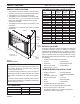
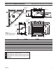
FIREPLACE & FRAMING DIMENSIONS
21”
( 533 mm)
2156O”
( 546 mm)
M in. R ough
O pening
D epth
6”
B- Vent
38"
( 965 mm)
34”
( 864 mm)
2156O”
( 546 mm)
B
A
3856O”
( 978 mm)
M in. R ough
O pening
H eigh t
1/2" or 5/8"
D ry w al l
Spacers
166M”
( 426 mm)
1456O”
( 368 mm)
26QE”
( 56 mm)
96”
( 244 mm)
624037
400BBV dims
D - M in. R ough O pening W idth
656O”
( 165 mm)
13(6QE”
( 341 mm)
E
F
G
G
6”
( 152 mm)
1/2” or 5/8”
D ry w al l
Spacers
C
Figure 3 -
400SBV, 500SBV Fireplace
and Framing Dimensions
Ref. 400SBV 500SBV
mm mm
mm mm
ZC\zn mm ZC\zn mm
D Z\x mm Z\x mm
Framing Dimensions
M\, mm M\, mm
mm mm
mm Z\v mm
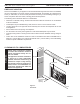
For easier installation on 400SBV and 500SBV
units, place gas supply pipe 6” to 8” inside
unit. Measure from the center of the gas
knock-out hole located at the bottom of the
left side.
NOTE