
Micronix PC/104 Power Supply User Manual & Installation Guide


Users Manual & Installation Guide
PV- 1075: N
I
MH
BATTERY PACK WITH CHARGER
Page 6 of 9
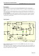
Connectors
The PV-1075 is equipped with four connectors:
Input connector (KL2)
Power into PV-1075 is supplied through KL2 that is a two-pole removable screw clamp connector.
The layout of this connector is shown on the connection drawing above. The voltage used must be
in the interval of 18-36V DC (PV-1075-CAR: 10.8V – 13.2V).
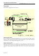
Output connector (KL1)
Mains power and battery power can be drawn from connector KL1 that is a three-pole removable
screw clamp connector. If used as a back-up module for Micronix PV-5127, this connector must be
connected to the power input connector (KL2), on PV-5127, as shown on the connection drawing
above.