
Micronix PC/104 Power Supply User Manual & Installation Guide


Users Manual & Installation Guide
PV- 1075: N
I
MH
BATTERY PACK WITH CHARGER
Page 7 of 9
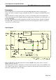
Battery connector (J1)
The NiMH battery is connected to PV-1075 using J1 that is a two-pole MOLEX connector. The
battery connector is disconnected at delivery to prevent deep discharge of the battery when not used
for a longer period.
PC/104 connector (CN1)
PV-1075 is attached the PC/104 stack using CN1. There are no electrical connection to this
connector and serves only to bypass the PC/104-bus in the stack.
Battery charger
The battery charger controls the charging process using two modes:
• standard charge mode with charging current = 50mA and
• trickle charge mode with charging current = 25mA.
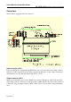
The switching between these modes is determined by a counter which is controlled by the
‘presence’ of mains. There are two input frequencies to this counter: one used during the presence
of mains input and one used when there are no mains input. The two frequencies have a mutual
ratio of 32 where the lowest frequency is used during count-up. During the presence of mains, the
counter counts up. When mains disappear, the counter counts down. The charging progress is
illustrated below:
Charging indicators
Two LEDs indicate the actual charging mode: D4 (yellow) indicate Standard Charge and D9
(green) indicate Trickle Charge. These LEDs are located on the component side.