User’s Manual 11N ADSL2+ Modem Router Model No.: SP3367N http://www.micronet.
Table of Contents Chapter 1 Introduction................................................................................. 2 1.1 Package Contents .......................................................................................... 2 1.2 Key Features ................................................................................................. 2 1.3 Safety Information ........................................................................................ 3 1.4 Specifications.........................
4.4.4 UPnP .................................................................................................................41 4.4.5 DDNS ................................................................................................................42 4.5 Maintenance ................................................................................................ 44 4.5.1 Administrator ....................................................................................................44 4.5.2 Time Zone ...
Certifications FCC This equipment has been tested and found to comply with Part 15 of the FCC Rules. Operation is subject to the following two conditions: (1) This device may not cause harmful interference (2) This device must accept any interference received. Include interference that may cause undesired operation. CE This equipment is in compliance with the requirements of the following regulations: EN 55 022: CLASS B.
Chapter 1 Introduction Micronet SP3367N, 11N ADSL2+ Modem Router, delivers highly reliable and scalable network environment. The model has incorporated both modem and router functions into a single unit with wireless support. It is compliant with IEEE 802.11 Draft-N and backward compatible with IEEE 802.11b/g. The wireless connection can be optimized up to highspeed data rate of 300Mbps for multimedia applications.
y ¾ PPP over AAL5 (RFC 2364). ¾ PPP over Ethernet (RFC 2516). Support 802.11n Wireless Access Point ¾ Complies with IEEE 802.11n draft 2.0, IEEE 802.11g and IEEE 802.11b standards. ¾ Farther coverage, less dead spaces and higher throughput with MIMO technology. ¾ High data rate – up to 300Mbps network speed. ¾ Supports 64-bit/128-bit WEP, WPA-PSK and WPA2-PSK wireless security functions. ¾ Supports WPS (WiFi Protected Setup) to easy connect wireless network without configuring the security.
y If users want to place this router at high places, please make sure the router is firmly secured. Falling from high places would damage the router and its accessories, and in such cases, the warranty will be void. y Accessories of this router, like antenna and power supply, are danger to small children under 3 years old. They may put the small parts in their nose or month and it could cause serious damage to them.
Sharing Virtual Server z DMZ z VPN Pass Through (IPSec/PPTP) z SPI Anti-DOS Firewall z ACL (Access Control) z IP/MAC/Application/URL Filter z UPnP (Universal Plug and Play) z Dynamic DNS z 64/128-bit WEP z WPA-PSK z WPA2-PSK z Web UI z SNMP 10~90% (Non-Condensing) 10~40℃ 12VDC, 1A Switch Power Adaptor FCC, CE z Security Features Management Humidity Temperature Power Certification 5
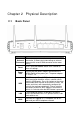
Chapter 2 Physical Description 2.1 Back Panel Parameter Antenna Connector Description The antenna connector of the router is reverse SMA connector. It allows you to connecting an external antenna with reverse SMA connector to the router easily. Reset Press and hold button for 5 seconds to clear all settings. Power Jack Please plug the power adapter attached with the ADSL Router to the power jack. The power adapter is 12VDC, 1A.
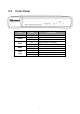
2.2 Front Panel LED Status PWR On Off Blinking Off Blinking On Blinking On Off Blinking WLAN WPS ADSL LAN (1-4) Description Device is switched on. Wireless LAN disabled. Wireless transmission detected. WPS function is disabled. WPS function is enabled. Successful connection to DSLAM. No connection. LAN port is connected. No network connection. Data is being sent or received.
Chapter 3 System and Network Setup 3.1 Build Network Connection Please follow the following instruction to build the network connection between the new wireless router and other network computers and devices: 1. Connect the ADSL port of modem router by telephone cable (RJ-11) to an outlet or splitter. 2. Connect all computers, network devices (network-enabled consumer devices other than computers, like game console, or switch / hub) to the LAN port of the router.
3. Connect the A/C power adapter to the wall socket, and then connect it to the ‘Power’ socket of the router. 4. The ADSL LED will be ON if the router is connected to the ADSL cable and receives the ADSL signals successfully. If the LED is blinking, please contact with your ISP (Internet Service Provider) to check the problem. 3.
3. Check the list of Network Components. If TCP/IP is not installed, click the button to install it. If TCP/IP is installed, go to step 6. 4. In the Network Component Type dialog box, select and click button. 5. In the Select Network Protocol dialog box, select and then click the button to start installing the TCP/IP protocol. Windows CD may be needed to complete the installation. 6. After installing TCP/IP, go back to the Network dialog box.
b) Windows 2000 1. Click the button and select , then click . The Control Panel window will appear. 2. Double-click icon. In the Network and Dial-up Connection window, double-click on icon. The Local Area Connection window will appear. 3. In the Local Area Connection window, click the button. 4. Check the list of Network Components. Users should see Internet Protocol [TCP/IP] on the list.
2. Double-click icon. The Local Area Connection window will appear. 3. Check the list of Network Components. Users should see Internet Protocol [TCP/IP] on the list. Select it and click the button. 4. In the Internet Protocol (TCP/IP) Properties window, select and as shown on the following screen. 5. Click to confirm the setting.
2. Select and , then click .
3.2.2 Router’s IP Address 1. After the IP address setup is complete, please click then at the bottom lower corner of the desktop. 2. Enter ‘cmd’ command and click . 3. Input ‘ipconfig’, then press ‘Enter’ key. Please check the IP address followed by ‘Default Gateway’ (In this example, the IP address of router is 192.168.2.1, please note that this value may be different).
3.2.3 Starting Web-Based Management UI 1. After the computer has obtained an IP address from router, please start the web browser. Input the IP address of router in the address bar and the following message should appear: 2. Please input username and password in the field respectively. Default username is ‘admin’ and default password is ‘1234’, then press button. Once the login details are entered correctly, users can see the web management interface of this router.
16
Chapter 4 Web-Based Management UI 4.1 Quick Start Wizard The Quick Start section is designed to get the broadband router running as quickly as possible. In the Quick Start, users are required to fill in only the information necessary to access the Internet. Once user clicks on the and click on , the following screen will appear. Step1: Set User Password Please enter the new password and confirm the password again.
Step 2: Time Zone The Time Zone allows router to base its time on the settings configured in this section. Click on to proceed to the next page: Broadband Type.
Step 3: Broadband Type In this section users have to select one of four types of connections that it will be using to connect to broadband router WAN port to the ISP (see screen below). Different ISPs require different methods of connecting to the Internet, please check with the ISP as to the type of connection it requires. Parameter Description Dynamic IP Address ISP will automatically provide an IP address. Static IP Address ISP has given users an IP address already.
Step 4 Enter the Internet account details provided by ISP Click to complete the Quick Start Wizard and restart modem router. 4.2 Interface Setup 4.2.1 Internet Below interface is for entering all parameters in regards to connecting to ISP devices for Internet. Please consult below tables for detail description of each parameter.
ATM VC Parameter Virtual Circuit VPI VCI Description VPI (Virtual Path Identifier) and VCI (Virtual Channel Identifier define a virtual circuit. VPI is a virtual path determines the way an ATM cell should be routed. The VPI is an 8-bit (in UNI) or 12-bit (in NNI) number that is included in the header of an ATM cell. The valid range for the VPI is 0 to 255. Enter the VPI assigned by the ISP. VCI is the label given to an ATM VC to identify it and determine its destination.
CBR (Constant Bit Rate) – This class is used for emulating circuit switching. The cell rate is constant with time. Select CBR to specify fixed (always on) bandwidth for voice or data traffic. UBR (Unspecified Bit Rate) – Select UBR for applications that are non-time sensitive, such as e-mail. ATM QoS PCR SCR MBS rtVBR (real time Variable Bit Rate) – This class is similar to nrtVBR but is designed for applications that are sensitive to cell-delay variation.
Parameter Description Service Name User Name Enter the name of your ISP. Password Enter the password that your ISP has assigned to you. Encapsulation Bridge Interface Connection TCP MSS Option Get IP Address Enter the username exactly as your ISP assigned. Please check with your ISP the method of multiplexing. In Bridge Mode, please select “1483 Bridge IP LLC” or “1483 Bridge IP VC-Mux”. In PPPoE/PPPoA mode, please select “PPPoE LLC”, “PPPoE VC-Mux”, “PPPoA LLC”, or “PPPoA VC-Mux”.
Dynamic Route Multicast MAC Spoofing Dynamic routing allows routing tables in routers to change as the possible routes change. This router supports RIP1, RIP2B and RIP2-M protocols for dynamic routing. After the RIP protocol is selected, please choose the RIP direction from “None”, “Both”, “IN Only” or “OUT Only”. Specify the method of transmitting data simultaneously to many receivers. Please select “IGMP v1” or “IGMP v2” as the multicast protocol or select “Disabled” to disable the function.
Dynamic Route Multicast IGMP Snoop Dynamic routing allows routing tables in routers to change as the possible routes change. This router supports RIP1, RIP2B and RIP2-M protocols for dynamic routing. After the RIP protocol is selected, please choose the RIP direction from “None”, “Both”, “IN Only” or “OUT Only”. Specify the method of transmitting data simultaneously to many receivers. Please select “IGMP v1” or “IGMP v2” as the multicast protocol or select “Disabled” to disable the function.
4.2.3 Wireless Access Point Settings Parameter Access Point Channel Beacon Interval RTS/CTS Threshold Fragmentation Threshold Description Activated or deactivated the wireless function of the router. When it is activated, the router will be an access point for other wireless clients to connect wirelessly. It is the radio channel used by the wireless LAN. All devices in the same wireless LAN should use the same channel.
Determines the interval the Access Point will send its broadcast traffic. The range is from 1 to 255 and the default value is 3 beacons. 802.11b – It only allows 802.11b wireless network client to connect to this router (maximum transfer rate 11Mbps). DTIM 802.11g – It only allows 802.11g wireless network client to connect to this router (maximum transfer rate 54Mbps). 802.11b+g – It only allows 802.11b and 802.11g wireless network client to connect to this router (maximum transfer rate 11Mbps for 802.
Broadcast SSID WMM Use WPS Select “Yes” to make the SSID to be visible so wireless clients can scan the router within the network. Select “No” if you want to hide the SSID of the router. Wireless clients have to set the same SSID of the router in order to access the network. The short of Wi-Fi Multi Media, it will enhance the data transfer performance of multimedia contents when they’re being transferred over wireless network. Select “Yes” to enable WPS function, Select “No” to disable WPS.
It’s very important to set wireless security settings properly. If not enabled, hackers and malicious users can reach your network and valuable data without user’s consent and this will cause serious security problem. Authentication Type This router supports WEP, WPA-PSK and WPA2-PSK authentication type. If the router has enabled the authentication, all the wireless clients’ settings have to be consistent with the router for building the connection.
Wireless MAC Address Filter Parameter Active Description This router can prevent the wireless clients from accessing the wireless network by checking the MAC Address of the clients. If users enable this function, please set the MAC Address of the wireless clients to be filtered. Allow Association – Only allow the wireless clients with the MAC Address specified to access the router.
4.3 Advanced Setup 4.3.1 Firewall Parameter Firewall SPI Description When you enable the firewall function, it will protect you from following attacks of WAN side: ¾ SYN flooding attack ¾ Ping of Death ¾ Teardrop ¾ Land attack If you enable SPI, all traffics initiated from WAN site will be blocked including DMZ, Virtual Server, etc. 4.3.
Routing Table List Users can see the current routing table of the router here. If they want to add another routing rule, please click “ADD ROUTE”. Parameter Dest IP Mask Gateway IP Metric Device Description Show the IP Address of the destination LAN. Show the Subnet Mask of the destination LAN. If it shows “8” that means the Subnet Mask is “255.0.0.0”; “16” means the Subnet Mask is “255.255.0.0”; “24” means the Subnet Mask is “255.255.255.0”. The next stop gateway of the path toward the destination LAN.
IP Subnet Mask Gateway IP Address Metric Announced in RIP Enter the Subnet Mask address of the destination LAN. This is the gateway IP Address where packets are sent. Enter the gateway IP Address and select the channel (PVC) you want to configure. The number of hops (routers) to pass through to reach the destination LAN. It must be between 1 and 15. Select “Yes”, this routing path will be propagated to other hosts through RIP broadcasts.
DMZ The DMZ Host is a local computer exposed to the Internet. When setting a particular internal IP Address as the DMZ Host, all incoming packets will be checked by the firewall and NAT algorithms then passed to the DMZ Host. For example, if you have a local client PC that cannot run an Internet application (e.g. Games) properly from behind the NAT firewall, then you can open the client up to unrestricted two-way Internet access by defining a DMZ Host.
Parameter Description Virtual Server for Show the Virtual Server setting is for single or multiple IP Addresses. Rule Index Choose the rule number. Application Select the application of the virtual server, for example: FTP or HTTP Server. When the application is selected, the port number for the application will be assigned automatically. Start Port Number Enter the start port number. End Port Number Enter the end port number.
4.3.4 ADSL Parameter ADSL Mode ADSL Type Description The default setting is “Auto Sync-Up”. This mode will automatically detect the ADSL mode including ADSL2+, ADSL2, G.DMT, T1.413 and G.lite. If you are not sure how to select the ADSL mode, please contact with your ISP. Check with your ISP about the ADSL type of the DSLAM device they use.
4.4 Access Management 4.4.1 ACL If users want to restrict users from accessing certain Internet applications/services such as Internet websites, email, FTP etc., then this is the place to set that configuration. Access Control allows users to define the traffic type permitted in your LAN or WAN. Users can control which computer can have access to these services by entering the IP Address of the computer. Parameter Description ACL Activate or deactivate the Access Control function.
4.4.2 Filter Users can forbid some users from accessing the router by filtering IP Address or MAC Address. Users can also restrict some applications or URLs be accessing by users through the router here. Please select the filter type to start configuring.
Parameter IP/MAC Filter Set Index Interface Description This is the item number to record the setting. Direction Select the access to the Internet (Outgoing) or from the Internet (Incoming), or Both. Select which channel (PVC) to configure. IP / MAC Filter Rule Editing Parameter Description IP/MAC Filter Rule This is the item number to record the setting rule. Index Rule Type Select to filter through the IP Address or MAC Address.
Parameter Application Filter ICQ/MSN/YMSG/ Real Audio/Video Description Activate or deactivate the application filter. If “Allow” is selected, the packets for these applications will be able to pass through the router. If you want to restrict these applications, please select “Deny”. URL Filter Parameter Active URL Index Description Activate or deactivate the URL filter. This is the item number to record the setting.
A URL can be thought of as the "address" of a web page and is sometimes referred to informally as a "web address." Please enter the web address here that you want to restrict to be connected. URL 4.4.3 SNMP Simple Network Management Protocol (SNMP) is a popular protocol for network management. It is used for collecting information and configuring the network devices. This router supports SNMP agent function, which allows a manager station to manage and monitor the router through the network.
Parameter UPnP Auto-configured Description Activated or deactivated the UPnP function. Select this check box to allow UPnP-enabled applications to automatically configure the router so that they can communicate through the router, for example by using NAT traversal, UPnP applications automatically reserve a NAT forwarding port in order to communicate with another UPnP enabled device. This eliminates the need to manually configure port forwarding for the UPnP enabled application. 4.4.
Parameter Description Dynamic DNS Service Provider Activated or deactivated the DDNS function. My Host Name Enter the domain name assigned to your router by the service provider. E-mail Address Enter the E-mail address assigned by DDNS service provider. Username Enter your username. Password Enter the password you set for the DDNS service. Wildcard Support Enable or disable the wildcard to stand for some characters. This router supports DynDNS service provider.
4.5 Maintenance 4.5.1 Administrator Parameter Description Username New Password The username of the router is “admin” by default. Confirm Password Enter the new password again to confirm the setting. Enter up to 30-digit for the new password. 4.5.2 Time Zone The Time Zone allows the router to set its time and this will affect function such as System Log.
Parameter Current Date/Time Synchronize time with Time Zone Description Show the current date/time of the router. NTP Server Automatically – Set the time automatically with a NTP Server. PC’s Clock – Set the time synchronize with computer. Manually – Set the time manually. Select the time zone of the country you are currently in. The router will set its time based on your selection. Daylight Saving Select this option if it is in daylight saving time.
4.5.4 System Restart In this interface, users can restart the router or restore to factory defaults. If users wish to restart the router using the factory default settings, select “Factory Default Settings” to reset to factory defaults. Users can also click the “Reset” button in the rear panel of the router over 5 seconds to reset default settings. 4.5.5 Diagnostics This page allows user to diagnose the connectivity of the LAN and WAN network.
4.6 Status 4.6.1 Device Info In this interface, it will show the device information including firmware, MAC Address, LAN and WAN settings and also the ADSL line status. 4.6.2 System Log Display system logs accumulated up to the present time. You can also save the logs for future reviewing.
4.6.3 Statistics Show the statistics of transmitted and received packets on the LAN port, ADSL line or WLAN port.
Chapter 5 Glossary 10Base-T It is an Ethernet standard for Local Area Network (LAN). 10Base-T uses a twisted pair cable with maximum length of 100 meters. AAL ATM Adaptation Layer that defines the rules governing segmentation and reassembly of data into cells. Different AAL types are suited to different traffic classes. ADSL Asymmetric Digital Subscriber Line, as its name showing, is an asymmetrical data transmission technology with high traffic rate downstream and low traffic rate upstream.
Default Gateway (Router) Every non-router IP device needs to configure a default gateway’s IP address. When the device sends out an IP packet, if the destination is not on the same network, the device has to send the packet to its default gateway, which will then send it out towards the destination. DHCP Dynamic Host Configuration Protocol, this protocol automatically gives every computer on your home network an IP address.
Idle Timeout Idle Timeout is designed so that after there is no traffic to the Internet for a pre-configured amount of time, the connection will automatically be disconnected. ISP Internet Service Provider is a business that provides connectivity to the Internet for individuals and other businesses or organizations. ISP Gateway Address The ISP Gateway Address is an IP address for the Internet router located at the ISP's office.
Application Protocol Port Number Telnet TCP 23 FTP TCP 21 SMTP TCP 25 POP3 TCP 110 H.323 TCP 1720 SNMP UCP 161 SNMP Trap UDP 162 HTTP TCP 80 PPTP TCP 1723 PC Anywhere TCP 5631 PC Anywhere UDP 5632 PPP PPP is the Point-to-Point-Protocol. The successor to SLIP, PPP provides router-to-router and host-to-network connections over both synchronous and asynchronous circuits.
RFC Request for Comments. The document (begun in 1969) is for describing the Internet suite of protocols and related experiments. Not all RFCs describe Internet standards, but all Internet standards are written up as RFCs. RFC 1483 Multi-protocol encapsulation over AAL-5. Two encapsulation methods for carrying network interconnect traffic over ATM AAL-5. The first method allows multiplexing of multiple protocols over a single ATM virtual circuit.
It is the virtual terminal protocol in the Internet suite of protocols. Allows users of one host to log into a remote host and act as normal terminal users of that host. VCI Virtual Circuit Identifier is part of the ATM cell header. A VCI is a tag indicating the channel over which a cell will travel. The VCI of a cell can be changed as it moves between switches via Signaling. VPI Virtual Path Identifier is part of the ATM cell header. A VPI is a pipe for a number of Virtual Circuits.