
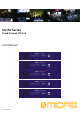
Operation Manual

9
User Manual
Please retain the original packing in case you should need to return the equipment to the manufacturer or supplier, or trans-
port or ship the unit later.
Installation
Before installing and operating this equipment, make sure it is correctly connected to the protective earth conductor of the
mains voltage supply socket outlet through each mains lead.
Ideally a cool area is preferred, away from power distribution equipment or other potential sources of interference.
Do not install the equipment in places of poor ventilation.
Do not install this equipment in a location subjected to excessive heat, dust or mechanical vibration. Allow for adequate venti-
lation around the equipment, making sure that its fans and vents are not obstructed. Whenever possible, keep the equipment
out of direct sunlight.
Mount in rack only.
Power
The internal power supplies are of the switch mode type that automatically senses the incoming mains voltage and will work
where the nominal voltage is in the range 100VAC to 240VAC.
The correct leads for connection in the area to which the unit was shipped are supplied with the unit. The equipment should
only be plugged into the mains outlets using the supplied leads.
Make sure the plug tted on the supplied mains cable is securely tted to the mains IEC connector on the unit. When tting or
removing a plug, always hold the plug itself and never use the cable, as this may damage it. Never insert or remove an electric
plug with wet hands.
Handling the equipment
When lifting or moving the equipment, always take its size and weight into consideration.
Completely isolate the equipment electrically and disconnect all cables from the equipment before moving it.
Do not insert your ngers or hands in any gaps or openings on the equipment, for example, vents.
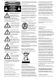
Electric elds
In accordance with Part 15 of the FCC Rules & Regulations, “… changes or modications not expressly approved by the party re-
sponsible for compliance could void the user’s authority to operate the equipment.”
Should this product be used in an electromagnetic eld that is amplitude modulated by an audio frequency signal (20Hz to
20kHz), the signal to noise ratio may be degraded. Degradation of up to 60dB at a frequency corresponding to the modulation
signal may be experienced under extreme conditions (3V/m, 90% modulation).
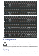
Connecting up
The DL150 Series uses the following leads and connectors:
Primary Analogue Inputs:
Mic/Line Inputs - Balanced XLR connectors - 10K load
Primary Analogue Outputs:
Main Outputs - Balanced XLR connectors - 50R Source
Primary Digital Inputs:
XLR connectors - 110R
AES50 Connections:
Neutrik Ethercons with status indication
Ethernet Control Connection:
Neutrik Ethercon with status indication
Diagnostics Connection:
9W Female ‘D’ type connector
Power Connections:
IEC mains inlet – 100-240V AC~50-60Hz
For further information about the connectors used in conjunction with the DL150 Series, see Section 5. Connectors.