Installation plan Tumble dryer PT 5135 C PT 7135 C To avoid the risk of accidents or damage to the machine, it is essential to read operating and installation instructions before installation and commissioning This prevents both personal injury and damage to the machine.
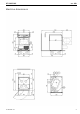
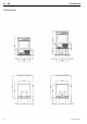
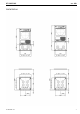
Legend: Connection optional or required, depending on model Connection required AL Vented KLZ Cooling air ASK Condensate drain hose PA Equipotential bonding B Machine anchors SLA Peak-load connection EL Electrical connection UG Box plinth F Machine feet, adjustable UO Open plinth KG Payment system WTV Washer-dryer stacking kit KGA Payment system connection XKM Communication module KLA Cooling air ZL Air intake All rights reserved.
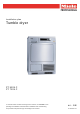
PT 5135/7135 en - GB Machine dimensions 10 145 320 / 01 3
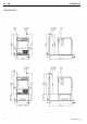
en - GB PT 5135/7135 Installation 4 10 145 320 / 01
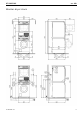
PT 5135/7135 en - GB Washer-dryer stack 10 145 320 / 01 5
en - GB PT 5135/7135 Installation 6 10 145 320 / 01
PT 5135/7135 en - GB Installation 10 145 320 / 01 7
en - GB PT 5135/7135 Technical data Drying system PT 5135 C Condensation PT 7135 C Condensation Drum volume l 130 130 Load capacity kg 6.5 6.5 Door opening diameter mm 391 391 Electrical connection (EL) Standard voltage 2N AC 400V 2N AC 400V Frequency Hz 50 50 Total rated load kW 3.68 3.68 Fuse rating (B trip rating according to EN 60898) A 2 x 10 2 x 10 Supply lead min. cross-section mm² 4 x 1.5 4 x 1.
PT 5135/7135 en - GB Technical data Standard voltage (FIN only) PT 5135 C - PT 7135 C 2N AC 400 V Frequency Hz - 50 Total rated load kW - 3.68 Fuse rating (B trip rating according to EN 60898) A - 2 x 10 Supply lead min. cross-section mm² - 4 x 1.5 - mm - 2000 Frequency Hz - 50 Total rated load kW - 3.68 Fuse rating (B trip rating according to EN 60898) A - 1 x 16 Supply lead min. cross-section mm² - 3 x 1.5 Frequency Hz - 50 Total rated load kW - 2.
en - GB PT 5135/7135 Technical data PT 5135 C PT 7135 C Installation on machine feet (F) No. of machine feet No. 4 4 Machine foot, height-adjustable with thread mm +14.5 / -7 +14.5 / -7 Machine foot diameter mm 40 40 Anchoring (B) Standard anchoring Wood screws according to DIN 571 mm 6 x 50 6 x 50 Rawl plugs (diameter x length) mm 8 x 40 8 x 40 Floor anchor kit (for 2 machine feet) Anchoring of Miele plinths Required anchor points No.
PT 5135/7135 Options / Accessories: en - GB Features Box plinth (UG) Box plinth, H 300 mm (UG 5005) Galvanised plinth, stainless-steel sides Box plinth, H 470 mm (UG 5005-47) Galvanised plinth, octoblue stove-finished side panels Box plinth, H 750 mm (UG 5005-75) Galvanised plinth, octoblue stove-finished side panels Open plinth (UO) Open plinth, H 300 mm (UO 5005) Galvanised plinth, octoblue stove finish Open plinth, H 470 mm (UO 5005-47) Galvanised plinth, octoblue stove finish W a s h e r -
en - GB PT 5135/7135 Installation and planning notes Installation requirements: Electrical connection should only be made to a power supply provided in accordance with all appropriate local and national legislation and regulations.
PT 5135/7135 The machine should be levelled in both directions with the aid of the adjustable feet. en - GB The quality of the concrete and its strength must be assessed according to the machine load. Ensure that any raised concrete plinth is adequately bonded to the concrete floor below! If the machine is installed on a concrete or masonry plinth, it must be secured using the anchors supplied with the machine. Otherwise there is the danger of the machine moving and falling off the plinth during spinning.