
installation plan
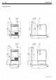
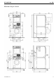
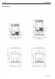
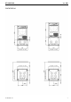


en - GB PT 5135/7135
12 10 145 320 / 01
Installation and planning notes
Installation requirements:
Electrical connection should only be made to a power supply provided
in accordance with all appropriate local and national legislation and
regulations.
In addition, all regulations issued by the appropriate utilities as well as
standards relating to occupational safety, and all applicable valid
regulations and technical standards must be observed!
General operating conditions
Ambient temperature in installation room: +2 °C to +35 °C.
This machine should not be operated in the same room as dry-
cleaning equipment using perchloroethylene or solvents containing
CFCs. Motor sparking may convert solvent vapours into hydrochloric
acid which can lead to consequential damage.
Electrical connection
Depending on the model, the machine is delivered with a supply lead
with/without a plug.
The washer may only be connected to an electrical system that
conforms to the national and local codes and regulations. The
installation must be performed by a qualified electrician.
The appliance data plate indicates the nominal power consumption
and the appropriate fuse capacity. Compare the specifications on the
data plate with those of the electrical power supply.
The machine can be hard-wired or connected using a switched
connection in accordance with IEC 60309-1. It is always
recommended to make electrical connection via a plug and socket so
that electrical safety checks, e.g. during repair or service work, can be
carried out easily.
If the machine is hard wired, a dual circuit breaker must be provided
on-site. When switched off there must be an all-pole contact gap of 3
mm in the isolator switch (including switch, fuses and relays according
to IEC/EN 60947).
The plug connectors or isolator switch should be easily accessible for
servicing work. If the machine is disconnected from the electricity
supply ensure adequate measures are taken to ensure that the
machine cannot be reconnected to the electricity supply until all work
has been carried out.
New connections, modifications to the system or servicing of the
ground conductor, including determining the correct fuse amperage,
must be carried out by a qualified electrician, as they are familiar with
the pertinent regulations and the specific requirements of the electric
utility company.
If converting the machine to an alternative voltage, observe the
instructions in the wiring diagram. Conversion must be performed
by an authorised agent or a Miele service technician. The heater
rating must also be properly set.
The machine must be permanently connected to the electricity supply
so that the door can be opened. For this reason, it must not be
connected to devices such as timers which would switch it off
automatically.
References to cable cross-sections in the technical data refer only to
the required supply lead. Please consult relevant local and national
regulations when calculating any other wire gauges.
Condensate drain hose
The machine drains through a pump with a 1 m delivery head. For the
water to drain freely, the hose must be free of kinks. The swivel elbow
at the end of the hose can be turned in either direction, or removed as
needed with a sharp twist and pull.
Drain hose connection:
1. Connected securely to a plastic drain pipe with a rubber sleeve.
There is no need for a U-pipe.
2. Connected to a sink using a plastic nipple.
3. Connected securely to a floor drain.
The drain hose with non-return valve fitted can be connected
directly to a suitable sink drain outlet.
The drain hose with non-return valve fitted can be connected securely
to a suitable sink drain outlet.
An adapter and hose clip is required and can be found at the bottom
of the dryer rear panel.
Equipotential bonding
If necessary, equipotential bonding with good galvanic contact must
be guaranteed in compliance with all applicable local and national
installation specifications.
Connection material for equipotential bonding must be provided on
site or using a kit available from Miele Spares.
Peak load/energy management
The machine can be connected to a peak-load or energy
management system using an optional kit.
Three signals are issued by the machine via a terminal strip. The
terminal strip is labelled a, b, c, and d.
a - Output signal, Start of machine operation
b - Output signal, Machine heating request
c - Peak-load input signal, Machine heating deactivated
d - Neutral conductor
When a peak-load signal is received, the heating is deactivated and
the programme stopped. An appropriate message appears in the
display.
The programme is resumed automatically when the peak-load system
reactivates the heating.
Payment system
This machine can be fitted with a single-machine payment system
(optional accessory). The necessary programming should only be
performed by a qualified agent or by Miele Service.
Serial interface
The serial interface is provided by an additional XKM RS323 module.
Connected external machines must also be fused in accordance with
SELV requirements. External connection units must also comply with
SELV.
The plug-in module is provided with a connection cable and a D-Sub
plug for connection.
Installation and anchoring
The machine must be installed on a perfectly smooth, level and firm
surface which is able to withstand the quoted loads.
The floor load created by the machine is concentrated and transferred
to the installation footprint via the machine feet.
It is not absolutely necessary to bolt the machine to the floor.