MIL-L800i 8-Port Power over Ethernet Injector Hub USER GUIDE
Regulatory Approval - FCC Class A - UL 1950 - CSA C22.2 No. 950 - EN60950 - CE - EN55022 Class A - EN55024 Canadian EMI Notice This Class A digital apparatus meets all the requirements of the Canadian Interference-Causing Equipment Regulations. Cet appareil numerique de la classe A respecte toutes les exigences du Reglement sur le materiel brouilleur du Canada.
Table of Contents 1. Introduction.............................................................................................................1 Features....................................................................................................................1 Package Contents.....................................................................................................2 2. Hardware Description.............................................................................................
1. Introduction Thank you for purchasing MiLAN Technology’s EmPoweredTM Series 8-port Power over Ethernet Injector Hub. Power-over-Ethernet (PoE) eliminates the need to run 110/220 VAC power to other devices on a wired LAN. Using Power-over-Ethernet, system installers need to run only a single CAT5 Ethernet cable that carries both power and data to each device. This allows greater flexibility in locating network devices and significantly decreases installation costs, in many cases.
Auto detect PD and classification of power consumption level Supports manual control of port power detection and classification Support automatic system calibration Support Auto MDI/MDI-X depends on the uplink switch port Centralized power distribution for PoE powered Device (PD) High safety short circuit protection to prevent cable short Supports IEEE 802.
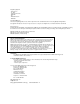
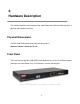
2. Hardware Description This Section describes the hardware of the 8 port Power over Ethernet Hub, and gives a physical and functional overview. Physical Dimensions The MIL-L800i PoE Injector Hub’s physical dimension is: 440mm x 224mm x 44mm (Lx W x H) Front Panel The Front Panel of the MIL-L800i PoE Injector Hub consists of 16x RJ-45 Ethernet ports (8xData In+8x Data+Power Out), LED indicators, and one console port. Figure 2-1.
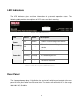
LED Indicators The LED Indicators gives real-time information of systematic operation status. The following table provides descriptions of LED status and their meaning. Figure 2-2. LED indicators LED Power Forwarding Power Off Status Color On Green Off -- Description Power is transmitting to the device Power is not transmitting to the device On Orange Device is overload or short. Blinking Orange It is detecting the PD. Off -- No device attached. Table 2-1.
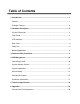
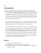
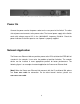
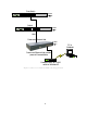
Figure 2-3 Rear panel of the 8 port Power over Ethernet Hub Power On Connect the power cord to the power socket on the rear panel of the Switch. The other side of power cord connects to the power outlet. The internal power supply of the Switch works with voltage range of AC in the 100-240VAC, frequency 50~60Hz. Check the power indicator on the front panel to see if power is properly supplied. Network Application The Power over Ethernet Hub can provides power to the PD that follow the IEEE 802.
8x 9x 1x 2x 3x 10x 11x 12x 7x 8x 9x 4x 5x 6x 1x 2x 3x 10x 11x 12x 4x 5x 6x AC power C 7 8 9 101112 A 12 34 56 A B Switch Ethernet Ethernet Core Switch 7x 7x 8x 9x 1x 2x 3x 10x 11x 12x 7x 8x 9x 4x 5x 6x 1x 2x 3x 10x 11x 12x 4x 5x 6x AC power C 7 8 9 101112 A 12 34 56 A B 100M Power over Ethernet Hub AC power PC or Notebook Power over Ethernet Hub provide power to Powered device POWERFAULT DATA ALARM Powered Device, ex: SOHO switch or Wireless AP
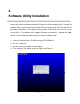
3. Software Utility Installation Berfore you start to remote configuring PD, please intsall the software utility. Through the software utility, you can easily to controll the PD that connect with PoE and view the PD parameter informations. The software utility provides GUI interface and user can easily to start with it. The software utility supports Windows environment -- Window 98, 2000, and XP. Please follow the below steps to install the software utility. 1.
5. Click the button to start installation. See Figure 3-2.
6. When installation finishes, click “OK” button to finish. See Figure 3-3. Figure 3-3 7. To run the software utility, go to “Star” Æ “Program” Æ “Power Over Ethernet series”. 8. If you want to remove the software utility, go to “Star” Æ “Control Panel” Æ “Remove/ Add application” Æ “Power Over Ethernet series”.
4. GUI Management Connecting to PoE Connecting the PoE with PC through the console port. Then, connect the PD (Powered Device) to the port of PoE. Run the software utility and select the COM port form Serial Link Setup function. You will see the main utility interface as figure 4-1. Figure 4-1. The GUI management interface The GUI management is divided into three parts: System Setup & Control: main system level parameters setup for the POE system.
Device Setting: you can save the device configuration to system, down load the device current configuration to the utility system and enable auto refresh function. Port Specific Control: each port specific function control and relate parameters display. Parametric Information: port parameters information display. System Setup & Control Calibrate System: when the system can’t do the port controlling, please remove the PD device and enable this function to calibrate internal system.
System Information Chip Version: display the system chipset version and revision information. Firmware Version: display the system firmware version. Utility Version: display the system utility version Total Port Power (W): total of all the port power that the system provided to PD. Figure 4-3.
Device Setting Enable Auto-Refresh: It allows the system auto refresh the system parameters. The system auto refresh in every 2 seconds. Load from Device : To get the last configuration value from device to the system utility. Save to Device : When you have configured the System Setup & Control and Port Specific Control, please press Save to Device configuration into the system.
Port Specific Control Port Enable: enabling the port. This function is co-responding with “Master Enable” function. Bypass Detection: bypass the detection function. Normally the system will try to detect the 25kΩ resistor in an 802.3af compliant PD device. If the PD doesn’t follow by IEEE 802.3af standard, you can enable this option to skip the detection on PD. When you enable this function, the system will not perform the 25Ω resistor detection for PD and directly transmit the power to PD.
LED Status Indicators: current LED indicator display – green, yellow, and red. The LED indicator will change depends on the PD status. ¾ Green: It represents PD is connecting with the POE hub system and working normally. ¾ Yellow: It represents there is no PD connecting with the port. ¾ RED: It represents PD’s power request is over the system support limit or the cable is short. Fault Status: display the PD error status message. There are three error status and explain as following.
Figure 4-5.
Parametric Information Discovery R (ohms): display resistance value. Port Current (mA): display current value. Port Voltage (V): display voltage value. Port Power (W): display watt value. Class Current (mA): display class current value. When you enable the “Bypass classification” function, the class current value will not show in here. Please refer to the following table for output value. Maximum power of levels at Class Usage 0 Default 15.4 Watts 1 Optional 4.
5. Technical Specification IEEE802.3af Power over Ethernet Standards IEEE802.3 10Base-T, IEEE 802.3u 100Base-TX Data in: 8 x RJ-45, Data pin 1,2,3,6 Connector Data and power out: 8 x RJ-45.
Null: no PD present or PD status is normal Fault status detect Overload: current support over 475mA @ DC 48V and over 50 milliseconds Mode status System detects status – I- sample, V-sample and R-detect It will show current PD parameters which Parametric information include Discover-resistor detected value, current, voltage, power consumption, classification current and determined class LED Power System: power Per port: power Forwarding, power off AC 100~240V, 50/60 Hz, 130 Watts, IEC power socket w
6. Appendix Console Port Pin Assignments The female DB-9 serial port on the POE hub front panel is used to connect to the switch for out-of-band console configuration. The web interface configuration program can be accessed from PC running the system utility program. The pin assignments used to connect to the serial port are provided in the following tables. Figure 6-1.
DB-9 Port Pin Assignments EIA Circuit CCITT Signal BB 104 Description Switch’s DB9 PC DB9 DTE Pin # RxD (Received Data) DTE Pin # 2 2 3 3 5 5 TxD BA 103 (Transmitted Data) AB SGND (Signal 102 Ground) NOTE: Remaining pins are not used.
90000429 Rev 1P