OM-263 001C 2014−06 Processes Multiprocess Welding Description Stationary Weld Fume Extractor ® FILTAIR Industrial Collector Series (230 Volt Models) Read And Save These Instructions File: Accessory Visit our website at www.MillerWelds.
From Miller to You Thank you and congratulations on choosing Miller. Now you can get the job done and get it done right. We know you don’t have time to do it any other way. That’s why when Niels Miller first started building arc welders in 1929, he made sure his products offered long-lasting value and superior quality. Like you, his customers couldn’t afford anything less. Miller products had to be more than the best they could be. They had to be the best you could buy.
TABLE OF CONTENTS SECTION 1 − SAFETY PRECAUTIONS - READ BEFORE USING . . . . . . . . . . . . . . . . . . . . . . . . . . . . . . . . . 1-1. Symbol Usage . . . . . . . . . . . . . . . . . . . . . . . . . . . . . . . . . . . . . . . . . . . . . . . . . . . . . . . . . . . . . . . . . . . . . . . 1-2. Fume Extraction Hazards . . . . . . . . . . . . . . . . . . . . . . . . . . . . . . . . . . . . . . . . . . . . . . . . . . . . . . . . . . . . . . 1-3. Arc Welding And Plasma Cutting Hazards . . . . . . . . . .
TABLE OF CONTENTS SECTION 7 − USER SERVICING INSTRUCTIONS (MAINTENANCE) . . . . . . . . . . . . . . . . . . . . . . . . . . . . . . 34 7-1. Routine Maintenance . . . . . . . . . . . . . . . . . . . . . . . . . . . . . . . . . . . . . . . . . . . . . . . . . . . . . . . . . . . . . . . . . 34 7-2. Replacing Filters . . . . . . . . . . . . . . . . . . . . . . . . . . . . . . . . . . . . . . . . . . . . . . . . . . . . . . . . . . . . . . . . . . . . . 35 7-3. Emptying Particle Bin . . . . . . . . . . . . . .
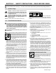
SECTION 1 − SAFETY PRECAUTIONS - READ BEFORE USING fume 2013−09 7 Protect yourself and others from injury — read, follow, and save these important safety precautions and operating instructions. 1-1. Symbol Usage DANGER! − Indicates a hazardous situation which, if not avoided, will result in death or serious injury. The possible hazards are shown in the adjoining symbols or explained in the text. Indicates a hazardous situation which, if not avoided, could result in death or serious injury.
FALLING EQUIPMENT can injure. Use equipment of adequate capacity to lift and support unit. If using lift forks to move unit, be sure forks are long enough to extend beyond opposite side of unit. Keep equipment (cables and cords) away from moving vehicles when working from an aerial location. Follow the guidelines in the Applications Manual for the Revised NIOSH Lifting Equation (Publication No. 94−110) when manually lifting heavy parts or equipment. MOVING PARTS can injure.
FUMES AND GASES can be hazardous. Do not weld or cut where the atmosphere may contain flammable dust, gas, or liquid vapors (such as gasoline). Welding and cutting produces fumes and gases. Breathing these fumes and gases can be hazardous to your health. Connect work cable to the work as close to the welding or cutting area as practical to prevent welding or cutting current from traveling long, possibly unknown paths and causing electric shock, sparks, and fire hazards.
ELECTRIC AND MAGNETIC FIELDS (EMF) can affect Implanted Medical Devices. Wearers of Pacemakers and other Implanted Medical Devices should keep away. Implanted Medical Device wearers should consult their doctor and the device manufacturer before going near arc welding, spot welding, gouging, plasma arc cutting, or induction heating operations. NOISE can damage hearing. Noise from some processes or equipment can damage hearing. Wear approved ear protection if noise level is high. 1-4.
READ INSTRUCTIONS. Read and follow all labels and the Owner’s Manual carefully before installing, operating, or servicing unit. Read the safety information at the beginning of the manual and in each section. Use only genuine replacement parts from the manufacturer. Perform maintenance and service according to the Owner’s Manuals, industry standards, and national, state, and local codes. Have the installation regularly checked and maintained.
SECTION 2 − MESURES DE SÉCURITÉ − EXTRACTION DES FUMÉES − À LIRE AVANT UTILISATION fume_2013−09_fre Se protéger et protéger les autres contre le risque de blessure — lisez, appliquez et rangez en lieu sûr ces consignes importantes de sécurité et d’utilisation. 2-1. Symboles utilisés DANGER! − Indique une situation dangereuse qui si on l’évite pas peut donner la mort ou des blessures graves. Les dangers possibles sont montrés par les symboles joints ou sont expliqués dans le texte.
nettoyants, les consommables, les produits de refroidissement, les dégraisseurs, les flux et les métaux. L’extracteur de fumées doit être utilisé avec le bras d’extraction, les tuyaux, le filtre et les autres composants recommandés par le fabricant. UNE DÉCHARGE ÉLECTRIQUE peut entraîner la mort. Le contact d’organes électriques sous tension peut provoquer des accidents mortels ou des brûlures graves.
Les câbles doivent être exempts d’humidité, d’huile et de graisse; protégez−les contre les étincelles et les pièces métalliques chaudes. Vérifier fréquemment le cordon d’alimentation afin de s’assurer qu’il n’est pas altéré ou à nu, le remplacer immédiatement s’il l’est. Un fil à nu peut entraîner la mort. L’équipement doit être hors tension lorsqu’il n’est pas utilisé. Ne pas utiliser des câbles usés, endommagés, de grosseur insuffisante ou mal épissés. Ne pas enrouler les câbles autour du corps.
Avant de souder, retirer toute substance combustible de vos poches telles qu’un allumeur au butane ou des allumettes. Une fois le travail achevé, assurez−vous qu’il ne reste aucune trace d’étincelles incandescentes ni de flammes. Utiliser exclusivement des fusibles ou coupe−circuits appropriés. Ne pas augmenter leur puissance; ne pas les ponter. Suivre les recommandations dans OSHA 1910.252(a)(2)(iv) et NFPA 51B pour les travaux à chaud et avoir de la surveillance et un extincteur à proximité.
Tenir l’équipement (câbles et cordons) à distance des véhicules mobiles lors de toute opération en hauteur. Suivre les consignes du Manuel des applications pour l’équation de levage NIOSH révisée (Publication Nº94–110) lors du levage manuelle de pièces ou équipements lourds. L’EMPLOI EXCESSIF peut SURCHAUFFER L’ÉQUIPEMENT. Prévoir une période de refroidissement ; respecter le cycle opératoire nominal. Réduire le courant ou le facteur de marche avant de poursuivre le soudage.
LE SOUDAGE À L’ARC ET LE COUPAGE PLASMA risquent de provoquer des interférences. LE RAYONNEMENT HAUTE FRÉQUENCE (H.F.) risque de provoquer des interférences. Le rayonnement haute fréquence (H.F.) peut provoquer des interférences avec les équipements de radio−navigation et de communication, les services de sécurité et les ordinateurs. Demander seulement à des personnes qualifiées familiarisées avec des équipements électroniques de faire fonctionner l’installation.
SECTION 3 − DEFINITIONS 3-1. Additional Safety Symbols And Definitions Keep away from pinch points. Safe110 2012−11 3-2.
SECTION 4 − SPECIFICATIONS 4-1. Introduction The industrial series of fume extractors come fully assembled and pre-wired, and are designed to easily integrate with existing equipment. These continuous-duty extractors use downward airflow through the extractor housing to deliver high filtration efficiency while using less energy. The rectangular filter packs, with proprietary filter media, can be pulse-cleaned on- or off-line.
4-4. Fume Extractor Specifications Model 2000 4000 8000 12000 15 (20) 20 (30) 230-Volt AC, 3-Phase, 60 Hz Input Power Horsepower 6000 5 (3) 7.5 (5, 10) 10 (15) Sound Level 71 − 74 dBA depending on HP. Peak-Cleaning Pulse Noise Is 92.7 dBA External Static Pressure See System Performance Curves in Section 4-5. Housing Construction 3/8 in. (9.525 mm) − 14 Gauge Steel Compliant With IBC2006 STD Housing Rating −15 in. −15 in. −15 in. Seismic Spectral Acceleration Ss = 1.5 S1 = 0.
4-5. Performance Curves B. Filtair 4000 12 12 11 11 10 10 External Static Pressure (in. wg) External Static Pressure (in. wg) A. Filtair 2000 9 8 7 6 5 4 3 2 3 HP 1 5 HP 0 500 1000 1500 2000 2500 Airflow (CFM) 3000 3500 7 6 5 4 3 10 HP 7.5 HP 2 5 HP 1 10 HP 15 HP 0 1000 2000 3000 4000 5000 Airflow (CFM) 6000 7000 D. Filtair 8000 External Static Pressure (in. wg) 14 13 12 11 10 9 8 7 6 5 4 3 2 1 0 4000 C. Filtair 6000 External Static Pressure (in.
SECTION 5 − INSTALLATION 5-1. Selecting A Location 3 2 1 Extend lifting forks beyond center of skid. ! ! Only qualified persons should install, operate, maintain, and repair this unit. Installation must meet all National, State, and Local Codes − have only qualified persons make this installation. ! Do not move or operate unit where it could tip. ! Do not use this equipment to support personnel, large tools, or other material. ! Use only the supplied control enclosures when installing this unit.
5-2. Clearance Requirements Minimum clearance requirements are the same for all models. Standard Model 8 in. (20 cm) w/HEPA Filter Option 24 in. (61 cm) w/Weather Hood Option 12 in. (30 cm) 8 in. (20 cm) 36 in. (91 cm) 36 in. (91 cm) 254 235-B 5-3. Lifting The Equipment 2 3 1 ! Lift only from the lifting eyes located at the top of the unit. Be sure location is clear of all obstructions, including utility lines and roof overhangs.
5-4. Mounting The Equipment ! Only qualified persons should install, operate, maintain, and repair this unit. ! Installation must meet all National, State, and Local Codes − have only qualified persons make this installation. ! Do not move or operate unit where it could tip. ! Do not use this equipment to support personnel, large tools, or other material. ! Use only the supplied control enclosures when installing this unit.
5-5. Connecting To Compressed Air Supply ! Shut off air supply before disconnecting or connecting air hose. ! Wear protective equipment when disconnecting compressed air supply. Internal air tank is under pressure and will discharge when air supply is disconnected. ! Close cover before starting unit or operating filter cleaning system. ! Do not direct air stream toward self or others. ! If ANY air is injected into the skin or body seek medical help immediately.
5-6. Electrical Service Guide − Filtair 2000 Elec Serv 2014−01 Failure to follow these electrical service guide recommendations could create an electric shock or fire hazard. These recommendations are for a dedicated circuit sized for the rated output of the equipment. 60 Hz Three Phase 3 HP Motor 5 HP Motor Input Voltage (V) 230 230 Input Amperes (A) At Rated Output 10.5 16.
5-8. Electrical Service Guide − Filtair 6000 Elec Serv 2014−01 Failure to follow these electrical service guide recommendations could create an electric shock or fire hazard. These recommendations are for a dedicated circuit sized for the rated output of the equipment. 60 Hz Three Phase 10 HP Motor 15 HP Motor Input Voltage (V) 230 230 Input Amperes (A) At Rated Output 28.9 42.
5-10. Electrical Service Guide − Filtair 12000 Elec Serv 2014−01 Failure to follow these electrical service guide recommendations could create an electric shock or fire hazard. These recommendations are for a dedicated circuit sized for the rated output of the equipment. 60 Hz Three Phase 20 HP Motor 230 Input Voltage (V) 54.
5-11. Making Electrical Connections To Unit Electrical Panel Tools Needed: ! 3/8 in. 3/8 in. 3 = GND/PE Earth Ground ! ! 8 ! 7 ! 10 ! 9 See input label on unit and check input voltage available at site. 1 4 Installation must meet all National and Local Codes − have only qualified persons make this installation. Disconnect and lockout/tagout input power before connecting input conductors from unit. Follow established procedures regarding the installation and removal of lockout/tagout devices.
SECTION 6 − OPERATION 6-1. Theory Of Operation 1 6 4 3 5 2 257188-A ! 1 2 Only use the fume extractor to extract weld fumes. Do not use the fume extractor to extract hot gases (above 140° F/60° C), wood or cement dust, engine exhaust, liquid vapors, explosive materials, aggressive fumes (acid), fumes from burning objects, or fumes from cleaning, cutting, gouging, grinding, painting, flame spraying, sand blasting, or other non-welding operations.
6-2. Controls And Components 1 Controller Interface See Sections 6-3 thru 6-9 for controller programming information. 2 Power Switch Turn switch to the On position to supply power to the fume extractor. 3 4 Start Button Stop Button Press Start button to turn fan blower on. Press Stop button to turn fan blower off. 5 Remote Control Switch Rotate switch to the Panel position to use front panel controls to turn fan blower on and off.
6-3. Controller − General Information “wg daPa Alarm Menu The controller monitors the differential pressure between the clean and dirty-air plenums to indicate the filter condition. It controls the pressure drop by turning the cleaning mechanism on and off at the set limits. There are three set points: High Pressure On, Low Pressure Off, and Alarm. High Pressure On and Low Pressure Off control the filter cleaning system.
6-4. Operating The Controller “wg daPa Alarm Menu Description The controller continuously monitors and displays differential pressure drop in inches of water or decaPascals on the panel face. When combined with a pulse timer, it can control the extractor cleaning mechanism to maintain the differential pressure drop between chosen limits. Three cleaning modes are available along with an alarm function and a 4 – 20 mA signal output.
6-5. Making Setpoint Adjustments 1 2 8 “wg daPa Alarm 3 Cleaning 7 4 Menu Set Downtime Clean 6 1 Display 2 Cleaning LED 3 Set Button 4 Downtime Clean Button 5 Decrease Setpoint Button 6 Increase Setpoint Button 7 Menu Button 8 Alarm LED Quick Start Instructions Press the Menu button, Lo appears. Press the Set button and the current value appears in the display. Use the arrow buttons to change this value.
6-6. Setpoint Adjustment Table Parameters Description Setting Range Factory Default Units All P6 Mode Select DTC Function All − Combines differential pressure P (ΔP) based cleaning with downtime cleaning On/Off selectable from keypad. All −− DTC − Filters down-time cleaned only, not based on filterΔP. DFF − filter cleaning based on ΔP with downtime cleaning not available. DFF P7 Display Units 0 = in. w.g. 1 = daPa 0 −1 0 −− Selects units of measure for the digital display.
6-7. Control Calibration 1 “wg daPa Alarm 3 Cleaning 2 Menu Set Downtime Clean 4 The only user calibration is the zero adjustment of the display. Slight changes in electronic components (over time) or pressure within the plant environment may cause the display to read something other than 0.0 while at rest. Use the following procedure to recalibrate the operating system.
6-8. Changing From English To Metric Units 1 “wg daPa Alarm 3 Cleaning 2 Menu Set Downtime Clean 4 To Change From English To Metric Units 1 Display 2 Menu Button 3 Set Button 4 5 Increase Button Decrease Button 5 Turn on power to the controller. Use the Menu button to select PAS. Press the Set button. Use the Increase and Decrease buttons to display “4”, then press the Set button again. Press the Menu button repeatedly until you reach P 6. Press the Set button.
6-9. Changing Optional Settings Board is located inside electrical panel. 1 8 7 6 5 2 3 4 257126-A Disconnect and lockout/tagout input power. Follow established procedures regarding the installation and removal of lockout/tagout devices. 1 Controller Circuit Board Open control panel access door and internal electrical panel to access circuit board.
6-10. Prestart Checklist (Before Welding) Do not use the fume extraction equipment unless you are sure it is correctly assembled and working properly. ! Do not look into the fan outlet to check fan rotation. View fan rotation through the top fo the inlet cone. (Fan should rotate counterclockwise.) Make sure the exhaust plenum is free of tools or debris before checking fan rotation. ! Keep away from exhaust outlet. Verify all ductwork and tubing is tight, secure, and does not leak.
SECTION 7 − USER SERVICING INSTRUCTIONS (MAINTENANCE) 7-1. Routine Maintenance ! Disconnect and lockout/tagout input power. Follow established procedures regarding the installation and removal of lockout/ tagout devices. ! Turn off compressed air supply and bleed air lines before servicing fume extractor. Bleed manifold air pressure to 0 psi (0 kPa). Service equipment more often if used in severe conditions.
7-2. Replacing Filters 5 3 2 5 4 1 Tools Needed: 6 Respirator ! ! Disconnect and lockout/tagout input power. Follow established procedures regarding the installation and removal of lockout/tagout devices. Turn off compressed air supply and bleed air lines before servicing fume extractor. Bleed manifold air pressure to 0 psi (0 kPa). ! Do not operate unit without filter or with dirty (plugged) filter. ! Clean or replace the filter when dirty (plugged).
7-3. Emptying Particle Bin 2 1 ! Disconnect and lockout/tagout input power. Follow established procedures regarding the installation and removal of lockout/ tagout devices. ! Do not operate unit without filter or with dirty (plugged) filter. ! Clean or replace filter when dirty (plugged). ! Allow cooling period before inspecting or replacing filter, or cleaning particle tray and spark guard. ! Do not breathe the particles collected by the fume extractor.
7-4. Overload Protection ! Filtair 2000 and 4000 Models Disconnect and lockout/tagout input power. Follow established procedures regarding the installation and removal of lockout/ tagout devices. Fuses are located inside electrical panel. 2 If a fuse or circuit breaker opens, it usually indicates a more serious problem exists. Contact a Factory Authorized Service Agent. 1 Fuse FU1 (All Models − Qty. 2) FU1 protects the 115 volt AC secondary control circuit from overload.
7-5. Sprinkler Installation (Optional) ! Disconnect and lockout/tagout input power. Follow established procedures regarding the installation and removal of lockout/ tagout devices. ! Sprinkler systems place a large quantity of water in the fume extractor when activated. Provide adequate drainage to remove water from facility. 4 1 NOTICE − Consult local authorities when installing fire control systems on fume extraction equipment. 2 3 Components shown from inside of housing.
7-6. Installing HEPA Filter Option ! Remove old sealant from panel. Disconnect and lockout/tagout input power. Follow established procedures regarding the installation and removal of lockout/ tagout devices. The high-efficiency HEPA filters are designed to capture small particulate and can only be used with the factory-installed HEPA exhaust plenum. Installation of the HEPA filter option is shown on a Filtair 8000. Installation is similar on all models.
SECTION 8 − TROUBLESHOOTING 8-1. Troubleshooting Table Trouble No display on controller. Remedy Check fuse FU1 in control panel. Replace fuse if open. Have Factory Authorized Service Agent check for proper supply voltage to controller. Optional Remote Control does not work. Place Remote Control switch on extractor in Remote position. Check fuse Fu2 in control panel. Replace fuse if open. Controller does not read zero when at rest. Recalibrate controller (see Section 6-7).
Trouble Remedy Down-time cleaning time is too long or too short. Reset parameter P10 on controller (see Section 6-5). Pressure display rapidly changes values. Reset parameter P12 on controller (see Section 6-5). Pressure drop does not go to zero at no-flow condition. Correct zero offset on controller. See parameter P13 and controller calibration information (Section 6-6. Place line disconnect switch in On position. Fan motor does not start Check for proper input power connections.
SECTION 9 − ELECTRICAL DIAGRAMS Figure 9-1.
265 329−A OM-263 001 Page 43
Figure 9-2.
265 357−A OM-263 001 Page 45
Figure 9-3.
265 335−A OM-263 001 Page 47
Figure 9-4. Circuit Diagram For Filtair 4000 (230V) 7.
265 336−A OM-263 001 Page 49
Figure 9-5.
265 358−A OM-263 001 Page 51
Figure 9-6.
265 339−A OM-263 001 Page 53
Figure 9-7.
265 360−A OM-263 001 Page 55
Figure 9-8.
265 346−A OM-263 001 Page 57
Figure 9-9.
263 037−A OM-263 001 Page 59
Figure 9-10.
265 353−A OM-263 001 Page 61
SECTION 10 − PARTS LIST Hardware is common and 22 23 Figure 10-1. Filtair 2000 Assembly OM-263 001 Page 62 19 20 21 26 See Figure 10-4 And Figure 10-5 24 See Figure 10-2 25 See Fig 10-3 18 17 OR 16 3 14 15 4 1 1 5 12 6 8 7 13 11 10 9 not available unless listed.
Item No. Dia. Mkgs. Part No. Description Quantity Figure 10-1. Filtair 2000 Assembly (Common Parts For All models) . . . 1 . . . . . . . . . . . . . . 257314 . . Roof Panel, Top Inlet Models Only . . . . . . . . . . . . . . . . . . . . . . . . . . . . . . . 1 . . . 1 . . . . . . . . . . . . . . 257319 . . Roof Panel, Front Inlet Models Only . . . . . . . . . . . . . . . . . . . . . . . . . . . . . . 1 . . . 3 . . . . . . . . . . . . . . 253293 . . Deflector . . . . . . . . . . . . . . . . . . . . . . .
Item No. Dia. Mkgs. Part No. Quantity Description Figure 10-1. Filtair 2000 Assembly (3 HP Parts) For Models 301107−001, 002, 011, And 013 . . . 20 . . . . . . . . . . . . . . 253630 . . Motor, Blower 3HP TEFC 208−230/460/60/3 . . . . . . . . . . . . . . . . . . . . . . . . 1 . . . 24 . . . . . . . . . . . . . Fig. 10-2 . . Delta P Plus Control, 230V 3HP 60Hz . . . . . . . . . . . . . . . . . . . . . . . . . . . . . . 1 Item No. Dia. Mkgs. Part No. Quantity Description Figure 10-1.
Item No. Dia. Mkgs. Part No. Description Quantity Figure 10-2. Filtair 2000 Controller (Figure 10-1, Item 24) (Common Parts For All Models) . . . 1 . . . . . . . . . . . . . . 252992 . . . . . 2 . . PLC1 . . . . . 254463 . . . . . 3 . SV1, SV2 . . . 254910 . . . . . 4 . . . TB1 . . . . . . 254462 . . . . . . . . . . . . . . . . . . . . . . 254461 . . . . . 5 . . . CR2 . . . . . . 254456 . . . . . 6 . . . CR1 . . . . . . 254455 . . . . . . . . . . . . . . . . . . . . . . 254457 . . . . . 7 . . . . . .
Hardware is common and not available unless listed. 7 1 8 2 3 6 4 5 Ref. 254 336-A Figure 10-3. Filtair 2000 Manifold Assembly Item No. Dia. Mkgs. Part No. Description Quantity Figure 10-3. Filtair 2000 Manifold Assembly (Figure 10-1, Item 25) (All Models) . . . 1 . . . . . . . . . . . . . . 253175 . . . 2 . . . . . . . . . . . . . . 253177 . . . 3 . . . . . . . . . . . . . . 269145 . . . 4 . . . . . . . . . . . . . . 253180 . . . 5 . . . . . . . . . . . . . . 253165 . . . 6 . . . . . . . . .
Hardware is common and not available unless listed. 6 1 2 3 5 4 7 Ref. 254 293-B Figure 10-4. Filtair 2000 Exhaust Plenum Item No. Dia. Mkgs. Part No. Description Quantity Figure 10-4. Filtair 2000 Exhaust Plenum (Figure 10-1, Item 26) For Models 301107−001, 003, 005, 006, 007, 008, 011 And 012 ... ... ... ... ... ... ... 1 2 3 4 5 6 7 .............. .............. .............. .............. .............. .............. ..............
Hardware is common and not available unless listed. 4 3 1 2 Ref. 254 255-C Figure 10-5. Filtair 2000 Exhaust Plenum w/HEPA Filter Item No. Dia. Mkgs. Part No. Description Quantity Figure 10-5. Filtair 2000 Exhaust Plenum w/HEPA Filter (Figure 10-1, Item 26) For Models 301107−002, 004, 013 And 014 ... ... ... ... 1 2 3 4 .............. .............. .............. .............. 253500 259470 300933 254209 .. .. .. .. Knob, Tri-lobe W/.312-18 Stud . . . . . . . . . . . . . . . . . . . . .
Notes OM-263 001 Page 69
9 Hardware is common and 16 21 26 27 22 24 23 See Figure 10-8 28 25 See Figure 10-7 29 See Figure 10-9 And Figure 10-10 19 20 18 17 OR 3 14 15 1 1 4 12 5 13 6 8 7 11 10 not available unless listed. 254 344-C Figure 10-6.
Item No. Dia. Mkgs. Part No. Quantity Description Figure 10-6. Filtair 4000 Main Assembly (Common Parts For All Models) . . . 1 . . . . . . . . . . . . . . 257315 . . Roof Panel, Top Inlet Models . . . . . . . . . . . . . . . . . . . . . . . . . . . . . . . . . . . . 1 . . . 1 . . . . . . . . . . . . . . 257319 . . Roof Panel, Front Inlet Models . . . . . . . . . . . . . . . . . . . . . . . . . . . . . . . . . . . 1 . . . 3 . . . . . . . . . . . . . . 253293 . . Deflector . . . . . . . . . . . . . . .
Item No. Dia. Mkgs. Part No. Description Quantity Figure 10-6. Filtair 4000 Assembly (5 HP Parts) For Models 301108−001, 002, 016, And 019 ... ... ... ... 19 . . . . . . . . . . . . . . 253189 20 . . . . . . . . . . . . . . 253324 21 . . . . . . . . . . . . . . 253208 25 . . . . . . . . . . . . . Fig.10-7 Item Dia. Part No. Mkgs. No. .. .. .. .. Fan Wheel, Alum Airfoil Sz 16 5HP 1.13 Bore . . . . . . . . . . . . . . . . . . . . . . . Bracket, Mount 5HP Blower Motor . . . . . . . . . . . . . . . . .
Hardware is common and 14 15 not available unless listed. 16 17 13 1 12 2 11 3 10 9 8 7 6 5 255 316-A 4 Figure 10-7. Filtair 4000 Controller Item No. Dia. Mkgs. Part No. Description Quantity Figure 10-7. Filtair 4000 Controller (Figure 10-6, Item 25) (Common Parts For All Models) . . . 1 . . . . . . . . . . . . . . 252998 . . . . . 2 . . . . . . . . . . . . . . 254450 . . . . . 3 . . . TB1 . . . . . . 254462 . . . . . . . . . . . . . . . . . . . . . . 254461 . . . . . 4 . . SV1−4 .
Item No. Dia. Mkgs. Part No. Description Quantity Figure 10-7. Filtair 4000 Controller (Common Parts For All Models) (Continued) . . . . . . . . . . . . . . . . . . . . 254465 . . . 15 . . ILPB1 . . . . . 254487 . . . 16 . . . PU1 . . . . . . 254458 . . . 17 . . . FU2 . . . . . *254459 . . . . . . . . . . . . . . . . . . . . 254460 . . . . . . . . . . . . . . . . . . . . 254481 . . . . . . . . . . . . . . . . . . . . 254482 . . . . . . . . . . . . . . . . . . . . 254483 . . . . . . . . . . . . . . . .
Hardware is common and not available unless listed. 8 7 1 2 3 4 6 5 Ref. 254 336-B Figure 10-8. Filtair 4000 Manifold Assembly Item No. Dia. Mkgs. Part No. Quantity Description Figure 10-8. Filtair 4000 Manifold Assembly (Figure 10-6, Item 24) (For All Models) . . . 1 . . . . . . . . . . . . . . 253175 . . . 2 . . . . . . . . . . . . . . 253177 . . . 3 . . . . . . . . . . . . . . 269145 . . . 4 . . . . . . . . . . . . . . 253180 . . . 5 . . . . . . . . . . . . . . 253165 . . . 6 . . . . . . .
Hardware is common and not available unless listed. 6 1 2 3 5 4 7 Ref. 254 293-B Figure 10-9. Filtair 4000 Exhaust Plenum Item No. Dia. Mkgs. Part No. Description Quantity Figure 10-9. Filtair 4000 Exhaust Plenum (Figure 10-6, Item 29) For Models 301108−001, 003, 005, 007, 008, 009, 010, 011, 012, 016, 017, And 018 ... ... ... ... ... ... ... 1 2 3 4 5 6 7 .............. .............. .............. .............. .............. .............. ..............
Hardware is common and not available unless listed. 4 3 2 1 Ref. 254 255-C Figure 10-10. Filtair 4000 Exhaust Plenum w/HEPA Filter Item No. Dia. Mkgs. Part No. Quantity Description Figure 10-10. Filtair 4000 Exhaust Plenum w/HEPA Filter (Figure 10-6, Item 29) For Models 301108−002, 004, 006, 019, 020, 021 ... ... ... ... 1 2 3 4 .............. .............. .............. .............. 253500 259470 300933 254210 .. .. .. .. Knob, Tri-lobe W/.312-18 Stud . . . . . . . . . . . . . . . . .
Hardware is common and 16 21 20 25 26 27 28 24-See Figure 10-12 23 −See Figure 10-13 29-See Figure 10-14 And Figure 10-15 22 19 18 17 OR 3 14 15 1 1 12 13 4 11 5 10 6 8 7 9 not available unless listed. 254 354-C Figure 10-11.
Item No. Dia. Mkgs. Part No. Quantity Description Figure 10-11. Filtair 6000 Main Assembly (Common Parts For All Models) . . . 1 . . . . . . . . . . . . . . 257316 . . Roof Panel, Top Inlet Models Only . . . . . . . . . . . . . . . . . . . . . . . . . . . . . . . 1 . . . 1 . . . . . . . . . . . . . . 257319 . . Roof Panel, Front Inlet Models Only . . . . . . . . . . . . . . . . . . . . . . . . . . . . . . 1 . . . 3 . . . . . . . . . . . . . . 253293 . . Deflector . . . . . . . . . . . . . . . . . . . .
Item No. Dia. Mkgs. Part No. Quantity Description Figure 10-11. Filtair 6000 Assembly (10 HP Parts) For Models 301109−001, 002, 011, And 013 ... ... ... ... 20 . . . . . . . . . . . . . . 253195 21 . . . . . . . . . . . . . . 253216 24 . . . . . . . . . . . . Fig.10-12 27 . . . . . . . . . . . . . . 253128 Item Dia. Part No. Mkgs. No. .. .. .. .. Fan Wheel, Alum Airfoil Sz 18 10HP 1.38 Bore . . . . . . . . . . . . . . . . . . . . . . Motor, Blower 10HP TEFC 208−230/460/60/3 1.38 Shaft . . . . . . .
Item No. Dia. Mkgs. Part No. Description Quantity Figure 10-12. Filtair 6000 Controller (Figure 10-11, Item 24) (Common Parts For All Models) . . . 1 . . . . . . . . . . . . . . 252999 . . . . . 2 . . PLC1 . . . . . 254451 . . . . . 3 . . . TB1 . . . . . . 254462 . . . . . . . . . . . . . . . . . . . . . . 254461 . . . . . 4 . . . CR2 . . . . . . 254456 . . . . . 5 . . . CR1 . . . . . . 254455 . . . . . . . . . . . . . . . . . . . . . . 254457 . . . . . 6 . . . . . . . . . . . . . . 254473 . . . . .
Hardware is common and not available unless listed. 10 9 1 2 3 7 4 8 6 5 Ref. 254 336-B Figure 10-13. Filtair 6000 Manifold Assembly Item No. Dia. Mkgs. Part No. Description Quantity Figure 10-13. Filtair 6000 Manifold Assembly (Figure 10-11, Item 23) (All Models) . . . 1 . . . . . . . . . . . . . . 253175 . . . 2 . . . . . . . . . . . . . . 253177 . . . 3 . . . . . . . . . . . . . . 269145 . . . 4 . . . . . . . . . . . . . . 253180 . . . 5 . . . . . . . . . . . . . . 253165 . . . 6 . . . . .
Hardware is common and not available unless listed. 6 1 2 3 4 5 7 Ref. 254 293-B Figure 10-14. Filtair 6000 Exhaust Plenum Item No. Dia. Mkgs. Part No. Description Quantity Figure 10-14. Filtair 6000 Exhaust Plenum (Figure 10-11, Item 29) For Models 301109−001, 003, 005, 006, 007, 008, 011, 012 ... ... ... ... ... ... ... 1 2 3 4 5 6 7 .............. .............. .............. .............. .............. .............. ..............
Hardware is common and not available unless listed. 4 5 3 2 1 Ref. 254 255-B Figure 10-15. Filtair 6000 Exhaust Plenum w/HEPA Filter Item No. Dia. Mkgs. Part No. Description Quantity Figure 10-15. Filtair 6000 Exhaust Plenum w/HEPA Filter (Figure 10-11, Item 29) For Models 301109−002, 004, 013, And 014 ... ... ... ... ... 1 2 3 4 5 .............. .............. .............. .............. .............. 253500 253507 300933 254226 254223 .. .. .. .. .. Knob, Tri-lobe W/.312-18 Stud . . .
Notes OM-263 001 Page 85
Hardware is common and 15 20 23−See Figure 10-17 Figure 10-16. Filtair 8000 Main Assembly OM-263 001 Page 86 24 25 26 27 29 −See Figure 10-19 And Figure 10-20 22 28 −See Figure 10-18 19 18 21 17 16 OR 14 3 1 1 13 12 4 11 8 5 6 7 10 9 not available unless listed.
Item No. Dia. Mkgs. Part No. Quantity Description Figure 10-16. Filtair 8000 Main Assembly (Common Parts For All Models) . . . 1 . . . . . . . . . . . . . . 257317 . . Roof Panel, Front Inlet Models Only . . . . . . . . . . . . . . . . . . . . . . . . . . . . . . 1 . . . 1 . . . . . . . . . . . . . . 257322 . . Roof Panel, Top Inlet Models Only . . . . . . . . . . . . . . . . . . . . . . . . . . . . . . . 1 . . . 3 . . . . . . . . . . . . . . 253293 . . Deflector . . . . . . . . . . . . . . . . . . . .
Item No. Dia. Mkgs. Part No. Quantity Description Figure 10-16. Filtair 8000 Assembly (15 HP Parts) For Models 301110−001, 002, 005, 007, 011, And 013 . . . 19 . . . . . . . . . . . . . . 253213 . . Motor, Blower 15HP Tefc 208−230/460/60/3 1.38 Shaft . . . . . . . . . . . . . . . 1 . . . 20 . . . . . . . . . . . . . . 253202 . . Fan Wheel, Alum Airfoil Sz 20 15hp 1.38 Bore . . . . . . . . . . . . . . . . . . . . . . 1 . . . 23 . . . . . . . . . . . . Fig.10-17 . . Delta P Plus Control, 460v 15HP . . .
Item No. Dia. Mkgs. Part No. Description Quantity Figure 10-17. Filtair 8000 Controller (Figure 10-16, Item 23) (Common Parts For All Models) . . . 1 . . . . . . . . . . . . . . 253000 . . . . . 2 . . PLC1 . . . . . 254452 . . . . . 3 . . . TB1 . . . . . . 255122 . . . . . . . . . . . . . . . . . . . . . . 254461 . . . . . 4 . . . CR2 . . . . . . 254456 . . . . . 5 . . . CR1 . . . . . . 254455 . . . . . . . . . . . . . . . . . . . . . . 254457 . . . . . 6 . . . . . . . . . . . . . . 254473 . . . . .
Hardware is common and not available unless listed. 10 9 1 2 3 7 4 8 6 5 Ref. 254 336-B Figure 10-18. Filtair 8000 Manifold Assembly Item No. Dia. Mkgs. Part No. Description Quantity Figure 10-18. Filtair 8000 Manifold Assembly (Figure 10-16, Item 28) (All Models) . . . 1 . . . . . . . . . . . . . . 253175 . . . 2 . . . . . . . . . . . . . . 253177 . . . 3 . . . . . . . . . . . . . . 269145 . . . 4 . . . . . . . . . . . . . . 253180 . . . 5 . . . . . . . . . . . . . . 253165 . . . 6 . . . .
Hardware is common and not available unless listed. 6 1 2 3 4 5 7 Ref. 254 293-B Figure 10-19. Filtair 8000 Exhaust Plenums (All Models Without HEPA) Item No. Dia. Mkgs. Part No. Quantity Description Figure 10-19. Filtair 8000 Exhaust Plenum (Figure 10-16, Item 29) (All Models) ... ... ... ... ... ... ... 1 2 3 4 5 6 7 .............. .............. .............. .............. .............. .............. .............. 253071 253072 253073 253078 253068 253070 254335 .. .. .. .. .. ..
Hardware is common and not available unless listed. 5 4 3 2 1 Ref. 254 255-B Figure 10-20. Filtair 8000 Exhaust Plenum w/HEPA Filter Item No. Dia. Mkgs. Part No. Description Quantity Figure 10-20. Filtair 8000 Exhaust Plenum w/HEPA Filter (Figure 10-16, Item 29) For Models 301110−002, 004, 013, And 014 ... ... ... ... ... 1 2 3 4 5 .............. .............. .............. .............. .............. 253500 253507 300933 254225 254224 .. .. .. .. .. Knob, Tri-lobe W/.312-18 Stud . . .
Notes OM-263 001 Page 93
OM-263 001 Page 94 Figure 10-21. Filtair 12000 Main Assembly 26 27 28 29 31 -See Figure 10-24 And Figure 10-25 25 -See Figure 10-22 30 -See Figure 10-23 23 24 21 22 20 19 1 18 16 17 4 OR 2 5 14 6 10 7 8 15 9 2 13 12 not available unless listed.
Item No. Dia. Mkgs. Part No. Quantity Description Figure 10-21. Filtair 12000 Main Assembly (Common Parts For All Models) . . . 1 . . . . . . . . . . . . . . 254120 . . Panel, Top . . . . . . . . . . . . . . . . . . . . . . . . . . . . . . . . . . . . . . . . . . . . . . . . . . . . . . 1 . . . 2 . . . . . . . . . . . . . . 257318 . . Roof Panel, Top Inlet Models Only . . . . . . . . . . . . . . . . . . . . . . . . . . . . . . . 1 . . . 2 . . . . . . . . . . . . . . 257323 . .
Item No. Dia. Mkgs. Part No. Quantity Description Figure 10-21. Filtair 12000 Assembly (20 HP Parts) For Models 301111−001, 002, 011, And 012 . . . 21 . . . . . . . . . . . . . . 253214 . . Motor, Blower 20HP Tefc 208−230/460/60/3 1.63 Shaft . . . . . . . . . . . . . . . 1 . . . 22 . . . . . . . . . . . . . . 253203 . . Fan Wheel, Alum Airfoil Sz 20 20HP 1.63 Bore . . . . . . . . . . . . . . . . . . . . . . 1 . . . 25 . . . . . . . . . . . . Fig.10-22 . . Delta P Plus Control, 230V 20HP . . . . . . . .
Item No. Dia. Mkgs. Part No. Description Quantity Figure 10-22. Filtair 12000 Controller (Figure 10-21, Item 25) (Common Parts For All Models) . . . 1 . . . . . . . . . . . . . . 253001 . . . . . 2 . . . . . . . . . . . . . . 254473 . . . . . 3 . . . CR1 . . . . . . 254455 . . . . . 4 . . . CR2 . . . . . . 254456 . . . . . . . . . . . . . . . . . . . . . . 254457 . . . . . 5 . . PLC1 . . . . . 254989 . . . . . 6 . TB1, TB2 . . . 254462 . . . . . . . . . . . . . . . . . . . . . . 254461 . . . . . 7 . .
Hardware is common and not available unless listed. 12 9 11 10 13 2 1 3 8 4 7 6 5 Ref. 254 336-B Figure 10-23. Filtair 12000 Manifold Assembly Item No. Dia. Mkgs. Part No. Description Quantity Figure 10-23. Filtair 12000 Manifold Assembly (Figure 10-21, Item 30) (All Models) . . . 1 . . . . . . . . . . . . . . 253175 . . . 2 . . . . . . . . . . . . . . 253177 . . . 3 . . . . . . . . . . . . . . 253181 . . . 4 . . . . . . . . . . . . . . 253180 . . . 5 . . . . . . . . . . . . . . 253165 . . .
Hardware is common and not available unless listed. 8 3 1 2 4 7 5 6 9 Ref. 254 293-A Figure 10-24. Filtair 12000 Exhaust Plenum Item No. Dia. Mkgs. Part No. Description Quantity Figure 10-24. Filtair 12000 Exhaust Plenum (Figure 10-21, Item 31) For Models 301111−001, 005, 007, 011 ... ... ... ... ... ... ... ... ... 1 2 3 4 5 6 7 8 9 .............. .............. .............. .............. .............. .............. .............. .............. ..............
Hardware is common and not available unless listed. 4 5 3 2 1 Ref. 254 255-B Figure 10-25. Filtair 12000 Exhaust Plenum w/HEPA Filter Item No. Dia. Mkgs. Part No. Description Quantity Figure 10-25. Filtair 12000 Exhaust Plenum w/HEPA Filter (Figure 10-21, Item 31) For Models 301111−002 And 013 ... ... ... ... ... 1 2 3 4 5 .............. .............. .............. .............. .............. 253500 253507 300933 254226 254228 .. .. .. .. .. Knob, Tri-lobe W/.312-18 Stud . . . . . . .
Effective January 1, 2014 (Equipment with a serial number preface of ME or newer) Warranty Questions? Call 1-800-4-A-MILLER for your local Miller distributor. Your distributor also gives you ... Service You always get the fast, reliable response you need. Most replacement parts can be in your hands in 24 hours. Support Need fast answers to the tough welding questions? Contact your distributor. The expertise of the distributor and Miller is there to help you, every step of the way.
Owner’s Record Please complete and retain with your personal records. Model Name Serial/Style Number Purchase Date (Date which equipment was delivered to original customer.) Distributor Address City State Zip For Service Contact a DISTRIBUTOR or SERVICE AGENCY near you. Always provide Model Name and Serial/Style Number. Contact your Distributor for: Welding Supplies and Consumables Options and Accessories Personal Safety Equipment Service and Repair Miller Electric Mfg. Co.