
Replacement Part List

1
3
4
3
4
2
5
6
7
8
9
10
11
12
13
14
15
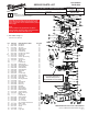
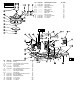
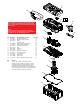
FIG. PART NO. DESCRIPTION OF PART NO. REQ.
1 14-38-0011 Top Cover Assembly (1)
2 14-38-0012 Middle Housing Assembly (1)
3 23-66-0011 Switch (1)
4 --------------- Middle Housing (1)
5 45-76-0030 Air Inlet Connector Assembly (1)
6 14-30-0303 Motor & PCBA Assembly (1)
7 14-38-0013 Bottom Base Assembly (1)
8 42-46-7015 Ball (1)
9 42-46-7020 Ball Cage (1)
10 49-90-1900 Filter (1)
11 43-44-0020 Bottom Base Gasket (1)
12 14-38-0014 Dirt Tank Assembly (1)
13 14-37-0105 Hose Assembly (1)
14 31-01-0875 Utility Tool (1)
15 31-01-0855 Crevice Tool (1)
16 12-20-0112 Service Nameplate (Not Shown) (1)
FIG. NOTES
16 A clean, dry surface is essential for proper
performance for any adhesive system. The area
intended for application of any adhesive label or
nameplate must be prepared by cleaning with
isopropyl alcohol. The solvent is to be applied with a
clean, lint free applicator and the surface allowed to
dry before applying the label or nameplate.
NOTE:
Model 0880-20 serial break "B" has two designs. If the
hose is stowed on the outside of the product, refer to
pages 1-2. If the hose can be stowed inside the product,
refer to page 3.
NOTE:
Filters are meant for dry applications only. Before
cleaning the lter, check the safety icon to determine if
your lter can be cleaned with water or not.