
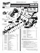
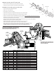
Service Parts List S/N B56B

Disassembly
3-15-25-36
Motor assembly [15] can be easily remove from gearcase assembly [25] by removing screws [3]
and loosening two screws [36] from the motor ball bearing [18] area of gearbox [25]
5 - 43
Before separating housing set [43] carefully cut thru the center of warning label [5] following the
seam of the housing halves
Reassembly
15 - 17 -25
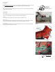
When reinstalling motor assembly [15] into gearcase assembly [25] make sure alignment pin side
of motor mounting plate [17] faces top of Gearcase assembly [25] (Fig. A)
29 -38
Press spindle guide pin [38] fl ush to outside casting of right gearcase [29]
20 - 23 - 45
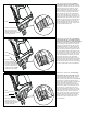
When reassembling switch assembly [20 / 23] into left motor housing half [45], place LED into
housing fi rst then position LED wiring into housing wire traps as shown in (Fig. B)
23 - 45 - 48
For proper back and forth movement of shuttle [48] PCB [23] must be inserted into left housing
half [45] support slots as shown in (Fig. C)
Pin
Top of Gearcase
LED
LED
Wire
Traps
Switch Assembly
[20, 23]
Left Housing
Half [45]
Lines on
PCB
Support
Slots
Shuttle [48]
Fig. A
Pin
Motor
Mounting
Plate
Motor Mount
Alignment Pin
orientation to
Gearcase Assembly
Fig. B
Fig. C
PCB Support slots found in Left
Housing Half must align with
lines on PCB for proper shuttle
movement