
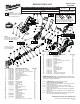
Service Parts List S/N B56B

1 Red ----- ----- Component of the Switch & PCB Assembly.
2 White ----- ----- Component of the Switch & PCB Assembly.
3 Red ----- ----- Component of the Switch & PCB Assembly.
4 White ----- ----- Component of the Switch & PCB Assembly.
5 Black ----- ----- Component of the Switch & PCB Assembly.
6 Red ----- ----- Component of the Switch & PCB Assembly.
7 Black ----- ----- Component of the Switch & PCB Assembly.
8 Gray ----- ----- Component of the Switch & PCB Assembly.
9 Green ----- ----- Component of the Switch & PCB Assembly.
10 Red ----- ----- Component of the Switch & PCB Assembly.
11 Black ----- ----- Component of the Switch & PCB Assembly.
12 White ----- ----- Component of the Switch & PCB Assembly.
13 Yellow ----- ----- Component of the Switch & PCB Assembly.
14 Blue ----- ----- Component of the Switch & PCB Assembly.
15 Black ----- ----- Component of the Switch & PCB Assembly.
16 Red ----- ----- Component of the Switch & PCB Assembly.
17 White ----- ----- Component of the Switch & PCB Assembly.
2
1
5
3
4
6
7
12
15
14
13
17
16
SWITCH
MOTOR
ASSEMBLY
PCB
ASSEMBLY
TERMINAL
BLOCK
LED
FUEL GAUGE
LED
8
9
10
11
Terminals, Connectors and 1 or 2 End Wire Preparation
Wire
Color
Origin or
Gauge
Wire
No.
Length
WIRING SPECIFICATIONS
AS AN AID TO REASSEMBLY, TAKE NOTICE OF
WIRE ROUTING AND POSITION IN WIRE GUIDES
AND TRAPS WHILE DISMANTLING TOOL.
BE CAREFUL AND AVOID PINCHING
WIRES BETWEEN HANDLE HALVES
WHEN ASSEMBLING.
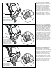
REMOVING THE STEEL QUIK-LOK
®
BLADE CLAMP
• Remove external retaining ring (12) and pull front cam (9) off.
• Pull lock pin (14) out and remove remainder of parts and discard.
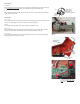
REASSEMBLY OF THE STEEL QUIK-LOK
®
BLADE CLAMP
• Coat new lock pin with powdered graphite.
• Hold tool in a vertical position.
• Place spring cover (8) onto spindle.
• Slide torsion spring (13) onto spindle with spring leg on hole side of spindle.
• Slide sleeve (11) onto spindle aligning hole on sleeve with hole in spindle.
• Slide rear cam (10) over sleeve until it bottoms on sleeve shoulder, ensure spring leg inserts into hole in rear cam.
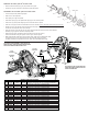
• Rotate rear cam in the direction of the arrows located on spring cover until there is clearance for lock pin (14) to be
inserted into sleeve/spindle holes. Insert lock pin.
• Align front cam (9) inner ribs with rear cam outer slots and slide front cam onto sleeve until it bottoms.
Retaining ring (12) groove should be completely visible.
• Attach retaining ring by separating coils and inserting end of ring into groove,
then wind remainder of ring into groove. Ensure ring is seated in groove.
• Blade clamp should rotate freely. During normal usage, debris may not allow blade clamp
to rotate freely. The use of spray lubricant can help free blade clamp. In extreme
conditions, follow these instructions to remove, clean and reassemble blade clamp.
Outer Slot
Leg
12
9
14
8
13
11
10