
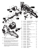
Replacement Part List
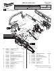

1 2
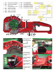
Wire Traps
3
4
9 8 7 6 515 14 13 12 11 10 Wire Traps
Wire Traps
Place wires #1 and
#2 completely in
bottom of wire traps.
Route red wire #6 in
wire trap of motor
housing.
Place wires #10,
#13, #14 and #15
in motor housing
wire trap.
Place #11 red wire
in motor housing
wire trap.
Place ribbon cable
in top of traps.
Place red wire #11
in the middle of
traps.
Place black wire #12
in bottom of wire
traps.
Motor Housing
Wire Traps
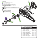
WIRING SCHEMATIC
1 Red Micro Switch/Control Board
2 Green Micro Switch/Control Board
3 Black Gearcase/Control Board
4 White Ribbon Cable
Control Board/Power Board
5 Red Switch/Control Board
6 Black Switch/ Control Board
7 White Switch/ Control Board
8 White Switch/ Control Board
9 White Switch/ Control Board
10 Black Terminal/SSD Board
11 Red Terminal/SSD Board
12 Red SSD Board/Power Board
13 Blue SSD Board/Control Board
14 Green SSD Board/Control Board
15 Black SSD Board/Control Board