
Replacement Part List
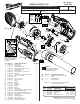

46a
Battery Terminal
Connector Block
46c
PCBA
46b
On-Off Switch
46d
Stator Assembly/
Hall Board
Nozzle Lock and
Nozzle Spring (26 and 28)
24 Speed Dial with
O-Rings (23) on each side
21 Trigger with
Compression Spring (20)
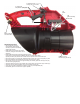
WIRING INSTRUCTIONS
• Place PCBA (46c) and the
On-Off Switch (46b) squarely
and rmly in place in the Housing
Support (30) cavities.
• Route wires from the Switch and PCBA
as shown, tucking the wires down into the
wire traps.
• Route PCBA wires along the Housing Support channel
(removing any slack) and place the Battery Terminal Connector Block (46a)
squarely and rmly into position. Be sure the wires are pushed down into the wire traps.
• Be sure the Trigger (21), Spring (20), Speed Dial with O-Rings (24 and 23) are properly in place.
• Be sure the Nozzle Lock and Nozzle Lock spring (26 and 28) are in place.
• Place Intake Vent Cover (19) onto Support Housing and carefully place the Housing Cover (15)
onto the Housing Support (30).
• Secure the Intake Vent Cover (19) between the housing halves using the two longer screws (34).
• Secure the housing halves together using 10 of the shorter screws (13).
• Check for the proper functionality of the Switch Trigger (21) and Speed Dial (24).
• Insert battery pack and check tool for proper operation.