
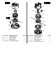
Replacement Parts List
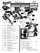

NOTE:
Rubber Pads (44-52-0001) are to be placed adhesive side down in recesses
of both housing halves prior to installation of motor/drive shaft assemblies.
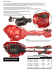
WIRING INSTRUCTION
• Place On-Off Switch (62a) and Two Speed Selector PCBA (62b) squarely and rmly in the cavities of the Support Housing (2).
• Route wires from those components through the wire traps in the Support Housing, removing as much slack in the wires along the way.
• The Rotor/Stator Assemblies (62d, 62e, 67) are captured in the Motor Insulator/Motor Mount Assemblies (65, 71). Place these
components squarely and rmly in the cavities of the Support Housing.
• Route wires from those components through wire traps in the Support Housing, removing as much slack in the wires along the way.
• Place Battery Connector/PCBA squarely and rmly in the cavity of the Support Housing.
• Be sure to tuck all wires and sleeved wire assemblies to the bottom of all wire traps.
• Carefully insert Drive Shaft Assembly (66) into the Rotor/Motor Mount Assembly (71). Be sure to orient Drive Shaft
so the two holes are perpendicular to the Support Housing. Tighten Hex Screw (28) with a 3mm hex wrench
to secure Drive Shaft to Motor Mount.
• Reinstall On-Off Trigger (25), Release Trigger (26) and Release Trigger Spring (31).
• Carefully place Housing Cover (12) onto Housing Support being sure to check for
any interferece and secure with Screws (13).
• Attach the Lower Cover Halves (63) with Screws (15).
• Check for the proper functionality of the On-Off Trigger (25) and Release Trigger (26).
• Install a battery pack and check the tool for proper operation.
ALWAYS REMOVE BATTERY PACK
BEFORE PERFORMING ANY
MAINTENANCE OR REPAIRS
SCREW TORQUE SPECIFICATIONS
SEAT TORQUE
FIG. PART NO. WHERE USED (KG/CM) (IN/LBS)
11 06-82-1080 Motor Insulator 12.0-16.0 10.4-13.8
13 05-88-1200 Housing Cover 15.0-20.0 13.0-17.3
15 05-88-1300 Lower Cover 15.0-20.0 13.0-17.3
16 05-88-5375 Housing Cover 15.0-20.0 13.0-17.3
24 06-82-7240 Motor Insulator 12.0-16.0 10.4-13.8
28 05-74-0013 Motor Mount 11.0-14.0 9.5-12.1
32 05-74-0015 Carrier Handle 25.0-28.0 21.6-24.3
32 05-74-0015 Gearcase Assy. 25.0-28.0 21.6-24.3
41 05-81-0131 Gearcase Assy. 20.0-25.0 17.3-21.6
42 05-85-0080 Gearcase Assy.
45 05-74-0935 Line Cut-Off Blade 15.0-20.0 13.0-17.3
46 05-81-0132 String Guard Assy. 28.0-32.0 24.3-27.7
53 --------------- Trimmer Head 145-155 125.8-134.5