OPERATOR'S MANUAL MANUEL de L'UTILISATEUR MANUAL del OPERADOR Cat. No. / No de cat. 2825-20 M18 FUEL™ ATTACHMENT SYSTEM W/ QUIK-LOK™ POWER HEAD SYSTÈME D’ACCESSOIRES M18 FUEL™ AVEC BLOC MOTEUR QUIK-LOK™ SISTEMA DE ACCESORIO M18 FUEL™ CON CABEZAL ELÉCTRICO QUIK-LOK™ WARNING To reduce the risk of injury, user must read and understand operator's manual. AVERTISSEMENT Afin de réduire le risque de blessures, l'utilisateur doit lire et bien comprendre le manuel.
•Remove any adjusting key or wrench before turning the power tool on. A wrench or a key left attached to a rotating part of the power tool may result in personal injury. •Do not overreach. Keep proper footing and balance at all times. This enables better control of the power tool in unexpected situations. •Dress properly. Do not wear loose clothing or jewelry. Keep your hair and clothing away from moving parts. Loose clothes, jewelry or long hair can be caught in moving parts.
•When battery pack is not in use, keep it away from other metal objects, like paper clips, coins, keys, nails, screws or other small metal objects, that can make a connection from one terminal to another. Shorting the battery terminals together may cause burns or a fire. •Under abusive conditions, liquid may be ejected from the battery; avoid contact. If contact accidentally occurs, flush with water. If liquid contacts eyes, additionally seek medical help.
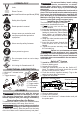
not use blades, brush cutting WARNING Do wheels, accessories, or attach- SYMBOLOGY ments other than those recommended by MILWAUKEE. Serious injury or product damage may occur. Do not operate the tool without the front handle in Direct Current place. The front handle must be attached properly No Load Revolutions per Minute (RPM) during use. Use both hands when operating the tool, according to the attachment instructions. Maintain a firm grip.
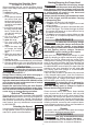
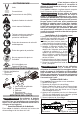
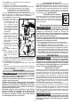
Starting/Stopping the Power Head Attaching the Shoulder Strap (Available as an accessory) When operating this tool, use the shoulder strap to reduce user fatigue and help in maintaining control during use. To install the strap: 1. Remove the battery pack. 2. Fit the pole clip around the power head pole between the front handle and rear handle in Gate a location comfortable Carabiner during use. Bevel Bolt 3. Insert the bolt through the pole clip and strap bevel.
SERVICE - UNITED STATES LIMITED WARRANTY - MEXICO, CENTRAL AMERICA & CARIBBEAN 1-800-SAWDUST (1.800.729.3878) TECHTRONIC INDUSTRIES' warranty is for 3 years since the original purchase date. This warranty card covers any defect in material and workmanship on this Product. To make this warranty valid, present this warranty card, sealed/ stamped by the distributor or store where you purchased the product, to the Authorized Service Center (ASC).
•Éviter tout contact avec des surfaces mises à la terre comme des tuyaux, des radiateurs, des cuisinières et des réfrigérateurs. Le risque de choc électrique est accru lorsque le corps est mis à la terre. •Ne pas exposer les outils électriques à l'eau ou l'humidité. La pénétration d’eau dans ces outils accroît le risque de choc électrique. •Ne pas maltraiter le cordon d'alimentation.
•Suivre toutes les instructions de charge et ne pas •Toujours tenir le visage, les mains et les pieds charger le bloc-piles ou l’outil en dehors de la plage loin des pièces en mouvement. Les pièces en de température spécifiée. Une charge incorrecte ou à mouvement peuvent provoquer des lacérations graves. des températures en dehors de la plage spécifiée peut •Les objets lancés pourront être projetés et endommager la pile et augmenter le risque d’incendie.
Il faut toujours retirer AVERTISSEMENT batterie et verrouiller la la détente de l’outil avant de changer ou d’enlever les accessoires. Pour insérer la batterie, la glisser dans le corps de l’outil. S’assurer qu’elle est fixée solidement. pas utiliser de lames, AVERTISSEMENT Ne de molettes de coupe à balais ni d'accessoires différent à ceux recommandés par MILWAUKEE. Des lésions graves ou dommages dans les produits pourront survenir. Ne pas opérer l’outil sans avoir premièrement installée la poignée avant.
Accessoires Quik-LokTM Pour retirer un accessoire ou une extension : 1. Retirer le bloc-piles. 2. Desserrer la poignée de verrouillage. 3. Appuyer sur le bouton de relâchement Quik-Lok™ et tirer des élagueuses pour les séparer. Cet outil peut être branché à un nombre d’accessoires Quik-LokTM MILWAUKEE. Utiliser seulement selon le manuel d’utilisation de l'accessoire.
Nettoyage À TOUTE GARANTIE IMPLICITE, Y COMPRIS, MAIS SANS S’Y LIMITER, TOUTE GARANTIE IMPLICITE DE QUALITÉ MARCHANDE OU D’ADAPTATION À UNE UTILISATION OU À UNE FIN PARTICULIÈRE. DANS LA MESURE OÙ UNE TELLE STIPULATION D’EXONÉRATION N’EST PAS PERMISE PAR LA LOI, LA DURÉE DE CES GARANTIES IMPLICITES EST LIMITÉE À LA PÉRIODE APPLICABLE DE LA GARANTIE EXPRESSE, TEL QUE CELA EST DÉCRIT PRÉCÉDEMMENT.
SEGURIDAD EN EL ÁREA DE TRABAJO control de la herramienta eléctrica en situaciones inesperadas. •Vístase adecuadamente. No utilice ropa o joyería holgada. Mantenga el cabello y la ropa alejados de las partes móviles. La ropa holgada, las alhajas o el cabello largo pueden quedarse atrapados en las partes móviles. •Si se proporcionan dispositivos para la conexión de instalaciones de extracción y recolección de polvo, cerciórese de que estén conectados y se utilicen correctamente.
•Utilice las herramientas eléctricas únicamente con baterías específicamente diseñadas. El uso de cualquier otra batería puede producir un riesgo de lesiones e incendio. •Cuando la batería no esté en uso, manténgala alejada de otros objetos metálicos como sujetapapeles, monedas, llaves, clavos, tornillos u otros objetos metálicos pequeños que puedan formar una conexión de una terminal a otra. Crear un corto entre las terminales de la batería puede ocasionar quemaduras o un incendio.
SIMBOLOGÍA ENSAMBLAJE la batería sólo con ADVERTENCIA Recargue el cargador especificado Volts para ella. Para instrucciones específicas sobre cómo cargar, lea el manual del operador suministrado con su cargador y la batería. Corriente continua Como se inserta/quita la batería en la herramienta Revoluciones por minuto sin carga (RPM) Para retirar la batería, presione los botones de liberación y jale de la batería para sacarla de la herramienta.
Botón de liberación Quik-Lok™ Accesorios Quik-LokTM Esta herramienta puede acoplarse a varios accesorios Quik-LokTM de MILWAUKEE. Utilice únicamente de conformidad con el manual del operador del accesorio. Se proveen especificaciones e instrucciones importantes de operación en el manual del accesorio. Utilice únicamente accesorios recomendados por Retén Cabezal eléctrico Manija para bloquear MILWAUKEE.
reducir el riesgo de leADVERTENCIA Para siones, descarga eléctrica o daño a la herramienta, nunca la sumerja en líquidos ni permita que estos fluyan dentro de la misma. Limpieza Limpie el polvo y suciedad de las ventilas. Mantenga los mangos limpios, secos y libres de aceite o grasa. Use solo jabón neutro y un trapo húmedo para limpiar, ya que algunos substancias y solventes limpiadores son dañinos a los plásticos y partes aislantes.
BULLETIN NO. SERVICE PARTS LIST 54-49-2810 REVISED BULLETIN SPECIFY CATALOG NO. AND SERIAL NO. WHEN ORDERING PARTS M18™ FUEL™ POWER UNIT STARTING CATALOG NO. 2825-21 K49A SERIAL NO.
No. 49-16-2718 Edge Trimmer Attachment FIG. 1 2 3 4 6 7 8 9 10 11 12 13 14 15 16 17 18 19 25 30 PART NO. 45-04-0016 43-34-2718 42-26-2718 43-78-0031 05-78-0029 05-78-0032 44-66-0038 43-54-0016 43-54-0018 14-29-0033 05-78-0033 42-40-0013 45-94-0017 45-88-0077 05-90-0016 43-98-0027 06-10-0012 42-36-0033 45-96-1001 45-08-0027 10-20-1782 DESCRIPTION OF PART NO. REQ. M8 x 15mm Hex Head LH Machine Screw (1) Blade Flange (1) Edger Blade (1) Edger Blade Mounting Hub (1) M5 x 8mm Pan Hd.
59 60 (2x) 61 14 (2x) 62 63 No. 49-16-2717 String Trimmer Attachment FIG. 14 15 30 41 57 57p 58 59 60 61 62 PART NO. 05-88-1200 05-74-0015 45-08-0028 05-81-0131 14-29-0038 05-85-0080 44-66-0139 --------------------------------------------------------- DESCRIPTION OF PART NO. REQ. M4 x 16mm Pan Hd. ST T-20 Screw (2) M6 x 21.5mm, 5mm Hex Socket Cap Screw (2) Drive Shaft Assembly (For String Trimmer) (1) M6 x 18mm, 5mm Hex Socket Cap Screw (1) Gearbox Assembly (1) M8 x 1.25 Hex Hd.
50 51 5 6 7 8 5 6 7 8 9 11 10 12 9 36 (2x) 17 20 15 18 26 17 13 21 (2x) (2x) 57 39 53 40 18 52 17 19 37 27 54 41 39 40 56 27 41 42 14 19 27 25 42 23 (2x) 24 (2x) 33 55 36 (2x) No. 49-16-2719 Hedge Trimmer Attachment FIG. 5 6 7 8 9 10 11 12 13 14 15 17 18 19 20 21 23 24 25 26 27 33 36 PART NO.
50 36 9 (3x) 51 36 12 8 (2x) 52 7g 9 7g 10 14 11 31 17 No. 49-16-2720 Pole Saw Attachment FIG. 7g 8 9 10 11 12 13 14 15 16 17 18 19 20 21 22 23 24 25 26 27 28 29 30 31 32 33 34 36 50 51 52 PART NO.
1 2 99 No. 49-16-2721 Extension Tube Attachment FIG. 1 2 3 4 5 6 7 8 13 98 99 PART NO. 05-81-0592 42-92-0047 45-72-0013 40-50-1090 44-60-0068 --------------05-78-0027 05-74-0026 45-88-0011 14-02-0010 45-08-0033 DESCRIPTION OF PART NO. REQ. M4 x 6.5mm Flat Head T-15 Screw (1) Trigger Cover (1) Quick Change Trigger (1) Spring (1) Clamping Knob (1) Quick Release Casting (1) M6 x 50mm Hex Hd. Machine Screw (1) M6 x 30mm Cap Hd.
SERVICE WIRING DIAGRAM Wire Traps and Channels Switch Assembly Wire Traps and Channels Make sure red wire is placed completely in wire trap. Red wire is connected to top terminal. Place wires in this order from top to bottom: 1. Blue wire 2. White wire 3. Black wire Red wire Place wires in this order from top to bottom: 1. Blue wire 2. Red Wire 3.