
Replacement Parts List


M18 FUEL™ Angle Grinder with Slide Switch & Lock-On
2881-20
L65A
54-38-7030
SEE PAGE 2
April 2021
REVISED BULLETIN
SERVICE PARTS LIST
BULLETIN NO.
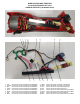
WIRING INSTRUCTION
DATE
SPECIFY CATALOG NO. AND SERIAL NO. WHEN ORDERING PARTS
CATALOG NO.
MILWAUKEE TOOL ● www.milwaukeetool.com
13135 W. Lisbon Road, Brookeld, WI 53005
Drwg. 1
STARTING
SERIAL NO.
FIG. PART NO. DESCRIPTION OF PART NO. REQ.
8 34-40-0330 O-Ring (1)
11 05-90-0225 Spring Washer (6)
12 05-78-5316 M4 x 14mm Pan Hd. Taptite T-20 Screw (4)
17 43-34-3000 Backing Flange (1)
18 44-40-7100 5/8" Flange Nut (1)
19 40-50-0386 Spring (1)
20 44-20-0091 Lock Tang (1)
21 45-04-0031 Shoulder Taptite Screw (1)
24 05-88-1255 M4 x 22mm Pan Hd. ST T-20 Screw (4)
25 02-40-0621 Ball Bearing (1)
26 44-86-2800 Bearing Retainer (1)
27 05-78-0105 M4 x 10mm Pan Hd. Tapt. T-20 Screw (2)
28 05-55-0620 Hex Nut (1)
29 --------------- Bevel Pinion (1)
30 45-88-0406 Washer (1)
31 --------------- Rotor (1)
32 02-04-0111 Ball Bearing (1)
35 06-82-1087 M3 x 12mm Pan Hd. ST T-10 Screw (1)
37 06-82-2025 M3.5 x 16mm Pan Hd. ST T-10 Screw (5)
38 42-42-0147 Lock-On Button (1)
39 40-50-0217 Spring (1)
FIG. PART NO. DESCRIPTION OF PART NO. REQ.
40 31-92-0226 Slide Pole (1)
41 --------------- Handle Cover (1)
42 --------------- Handle Support (1)
43 31-15-0103 Dust Cover (1)
45 42-62-0125 Side Handle (1)
46 43-54-1221 5” Type 27 Guard Assembly (Std Equip Shown) (1)
43-54-4010 Clip-On Guard (Not Shown) (1)
43-54-1230
5" Type 1 Guard Assembly (Optional, Not Shown)
(1)
43-54-1200
4.5" Type 27 Guard Assembly (Optional, Not Shown (1)
43-54-1210
4.5" Type 1 Guard Assembly (Optional, Not Shown)
(1)
48 49-96-7215 Wrench (1)
53 14-73-2000 Spindle Hub Assembly (1)
54 14-20-5031 Electronics Assembly (1)
55 14-38-2601 Housing Kit (1)
56 14-30-1110 Gearcase Assembly (1)
57 23-40-6010 Rotor Assy Kit (1)
59 14-62-0300 Bearing Retainer Kit (1)
61 12-20-0285 Service Nameplate (1)
62 50-55-3560 Contractor Bag (1)
35 37 41
42 61
55
60
43
54
41
38
61
37
(5x)
62
43
42
45
11
(4x)
12
(4x)
19
20
21
46
17
18
48
8 19 20
21 29
53
8
11
(2x)
27
(2x)
56
25
24
(4x)
28
29
57
31
32
25
26
30
31
59
11 26
27
32
35
39
40
*LUBRICATION NOTE:
When servicing the Gear Case Assembly,
90-95% of the old grease must be removed
prior to new grease being added.
FIG. LUBRICATION*
56 Type ‘J’ Grease, No. 49-08-4220, 1 lb. can.
Place approximately 16 grams (.562 oz.) in
gearcase cavity, being sure to completely coat
all teeth of bevel pinion and surrounding area.
EXAMPLE:
Component Parts (Small #) Are Included
When Ordering The Assembly (Large #).
0
00