
Use and Care Manual

6
7
ASSEMBLY
WARNING To reduce the risk of injury,
always unplug tool before attaching
or removing accessories or making adjust-
ments. Use only specifi cally recommended
accessories. Others may be hazardous.
WARNING To reduce the risk of
injury, do not remove accessory tips until
tool has cooled to room temperature.
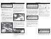
Installing Reduction Nozzles
Reduction nozzles are used to intensify the applica-
tion of heat in a specifi c area.
For reduction nozzle 49-80-0297:
1. To install the reduction nozzle to the heat gun,
slide the nozzle onto the heat gun nose.
2. Adjust heat, distance and length of application
as necessary.
For reduction nozzles 49-80-0305, 49-80-0306
(For use with electronic controlled heat guns 8978,
8986-20 and 8988-20 only):
1. To install the reduction nozzle to the heat gun,
align the grooves on the nozzle with the grooves
on the heat gun nose.
2. Slide the nozzle onto the nose.
3. Adjust heat, distance and length of application
as necessary.
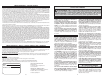
Installing Slit and Cutting Nozzles
The slit nozzle 49-80-0308 is used for lap welding.
The cutting nozzle 49-80-0309 is used as a heated
cutting edge.
NOTE: The reduction nozzle 49-80-0305 is needed
as an attachment for the slit and cutting nozzles.
(For use with electronic controlled heat guns 8978,
8986-20 and 8988-20 only):
1. To install the reduction nozzle to the heat gun,
align the grooves on the nozzle with the grooves
on the heat gun nose and slide the nozzle onto
the nose.
2. Slide the slit or cutting nozzle onto the reduction
nozzle.
3. Adjust heat, distance and length of application
as necessary.
SYMBOLOGY
Double Insulated Canadian Standards Association
Volts Alternating Current Underwriters Laboratories, Inc.
Amps
Underwriters Laboratories, Inc.
United States and Canada
Watts
OPERATION
WARNING To reduce the risk of injury,
always unplug tool before attaching
or removing accessories or making adjust-
ments. Use only specifi cally recommended
accessories. Others may be hazardous.
WARNING To reduce the risk of injury,
wear safety goggles or glasses with side
shields.
Cat. No. 8977
Variable temperature model heat
guns are marked “O” for OFF and
“l” for ON. Temperature is con-
trolled by turning the end cap in the
directions dictated by the arrows.
Cat. No. 8978
Electronic temperature control system heat guns
allow the tool to produce a greater concentration
of heat at the nozzle, allowing the use of various
accessory nozzles.
The electronic control system regulates the tem-
perature within the tool’s heating element. Unlike
non-electronic heat guns, MILWAUKEE’s electronic
heat gun will maintain the same temperature even
when the air fl ow is decreased or restricted with
the use of accessory nozzles.
Cat. No. 8978 is a variable temperature heat gun
with a range between 200° F and 1100° F (93° C
to 593° C). The heat adjustment knob is a dial with
numbers 1 through 6 on it as shown. The lower
numbers correspond to cooler temperatures and
higher numbers correspond to warmer tempera-
tures. To adjust temperature, simply turn the dial
to the left or the right.
Cat. No. 8986-20 and 8988-20
These heat guns have a variable temperature
control switch, which allows the user to adjust the
temperature for specifi c applications.
The electronic temperature control system regu-
lates the temperature within the tool's heat-
ing element. Unlike non-electronic heat guns,
MILWAUKEE's electronic heat gun will main-
tain the same temperature even when the air
flow is decreased or restricted with the use of
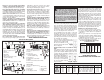
accessory nozzles. Refer to the airfl ow/temperature
chart for various airfl ow and temperature settings.
On Cat. No. 8988-20, a temperature display shows
the heat gun temperature setting.
1. Slide the airfl ow control switch (blue switch)
to Position II or III to operate the temperature
control switch.
2. To adjust the temperature, slide the temperature
control switch (red switch) to the desired posi-
tion.
When the temperature control switch is set to the
desired position on the 8988-20, the temperature
for that position will show on the temperature
display. After 3 seconds, the temperature display
will show the heat gun’s actual temperature. The
temperature display will continue to show the
actual temperature as the heat gun adjusts to the
desired temperature set by the temperature control
switch position.
O = Off
I = Low Temp.
570° F
I I = High Temp.
1000° F
O = Off
I = On
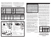
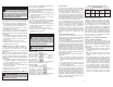
Airfl ow/Temperature Settings (8986-20 & 8988-20)
Airfl ow
Control
Switch
Setting
Position I
Position II
Position III
Airfl ow
Fan
Speed
High
Low
High
Minimum
Temp.
Setting
90°F
90°F
90°F
Maximum
Temp.
Setting
90°F
1100°F
1100°F
Air Flow at
Maximum
Temp.
Setting
7 CFM*
8.8 CFM
16 CFM
* Cubic feet per minute
Using the Airfl ow Control Switch
(Cat. No. 8986-20 & 8988-20)
Cat. No. 8986-20 & 8988-20 have three airfl ow
settings: high without heat, low with heat and high
with heat. Refer to the airfl ow/temperature chart for
various airfl ow and temperature settings.
1. For high airfl ow without heat, slide the airfl ow
control switch (blue switch) to Position I.
NOTE: The temperature control switch (red
switch) will not operate in this position.
2. For low airfl ow with heat, slide the airfl ow control
switch (blue switch) to Position II. The tempera-
ture may be adjusted from 90°F to 1100°F using
the temperature control switch (red switch).
The airfl ow will automatically increase as the
temperature increases.
3. For high airfl ow with heat, slide the airfl ow control
switch (blue switch) to Position III. The tempera-
ture may be adjusted from 90°F to 1100°F using
the temperature control switch (red switch).
The airfl ow will automatically increase as the
temperature increases.
4. To turn the heat gun off, slide the airfl ow control
switch (blue switch) to Position 0.
Selecting Temperature
The proper amount of heat for each application de-
pends on the temperature range selected, distance
between the nozzle and workpiece, and the length of
time heat is applied. Experiment with scrap materials
and start with lowest temperature range. Be cautious
when working until the proper combination of heat,
distance and time of application has been obtained.
Use a back and forth motion when applying heat
unless concentrated heat is desirable.
Support Stand (Cat. Nos. 8975 and 8977)
Cat. Nos. 8975 and 8977 have a support stand,
which allows you to position the heat gun upright
on a workbench, leaving both hands free for your
application. When using Cat. Nos. 8975 and 8977
on a workbench, always place tool on a fl at surface
and snap the support stand into the notched posi-
tion. Place the cord so the heat gun won’t tip. The
rear vent openings are designed to allow air fl ow
even when the tool is resting on the end cap, but
it is important not to cover the vents with foreign
materials such as clothing or rags. Cat. No. 8978
has a fl at bottom surface that acts as a support
stand. Rest the tool on the fl at surface, making sure
to place the cord so the heat gun won’t tip.
Installing Air Directing Nozzles
Air directing nozzles are used to change the direc-
tion of the airfl ow.
For hook nozzle 49-80-0292, defl ector 49-80-0293,
air spreader 49-80-0294, soldering refl ector nozzle
49-80-0307:
1. To install an air directing nozzle to the heat gun,
slide the nozzle onto the heat gun nose.
2. Adjust heat, distance and length of application
as necessary.
For air refl ector Cat. No. 49-80-0307 (For use with
electronic controlled heat guns 8978, 8986-20 and
8988-20 only):
1. To install the air refl ector nozzle to the heat gun,
align the grooves on the nozzle with the grooves
on the heat gun nose.
2. Slide the nozzle onto the nose.
3. Adjust heat, distance and length of application
as necessary.
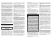
Using the Temperature Control Switch
Cat. No. 8975
Dual temperature control
heat guns have a 3 posi-
tion rocker switch. Place
the switch in the center
position for “Low” range or
press in the lower position
of the switch completely for
“High” range.