
Instruction manual


Adaptto E-drives Lab. 2013
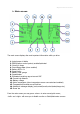
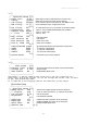
7. Connectors and pin-outs
1) Positive power lead (red housing male)
2) Negative power lead (black housing male)
3) BMS connector (red heat shrink)
4) Display connector (blue heat shrink)
5) Hall\motor connector
6) Negative charge lead (black housing female)
7) motor phase 1 (blue housing female)
8) motor phase 2 (blue housing female)
9) motor phase 3 (blue housing female)
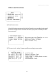
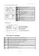
Hall\motor connector pin-out (male motor side):
1) hall 1
2) hall 2
3) hall 3
4) motor temperature sensor
5) GND
6) +5v
Throttle\E-brake connector pin-out:
1) +5v (brown wire)
2) Brake hall out (white wire)
3) GND (black wire)
4) Throttle hall out (blue wire)
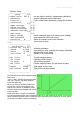
USB female connector
Uses regular pin-out with shorted data+ and data- for most phones compatibility.
12