
Installation Sheet

2
Fig.1
INSTALLATION INSTRUCTIONS
Item#2388-77(New.09/14/2017)
READ AND SAVE THESE INSTRUCTIONS
WARNING! SHUT POWER OFF AT FUSE OR CIRCUIT BREAKER.
AVERTISSEMENT! COUPER LE COURANT AU NIVEAU DES FUSIBLES OU DU DISJONCTEUR.
Fig. 2
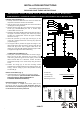
HANGING THE FIXTURE (Fig. 1)
1. Carefully remove the fixture from the carton and check that
all parts are included as shown in the illustration.
2. Shut off power at the circuit breaker and remove old fixture
including the mounting hardware.
3. Attached circular strap (B) to the outlet box using mounting
screws (K)( size:8/32*25mm).The side of circular strap
marked “GND” must face out.
4. Determine the desired handing height and thread rods (F3) to
the nipple of the fixture body (G), Then attach loop (L3) by
screwing in to rod(F1).Note: remove the nipple if installing
with one 6’ rod only.
5. Attach the quick link (L) to loop (L3) and loop (L1) on the
canopy (D), carefully feed the wire over loop (L3), quick link
(L2) and loop (L1).
6. The support cable is provided to support the weight of the
fixture while wiring. Align the fixture to circular strap (B) and
attach hook (M) on the end of support cable into a slot
located on circular strap (B).Carefully allow the support cable
to support the weight of the fixture while wiring.
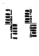
CONNECTING THE WIRES (Fig. 2)
7. At this point, connect the electrical wires as shown in (Fig.2),
Make sure that all wire connections are secured. If your
outlet has a ground wire (green or bare copper), connect the
fixtures Ground Wire to it. Otherwise, connect the fixture
Ground Wire directly to the circular strap using the Green
Screw.
8. Position the canopy (D)
so that the mounting screws
protruding from mounting bracket line up with the holes in the
canopy. Secure canopy in place with provided mounting
screws balls (E)
INSTALL LIGHT BULB (Fig. 1)
9. Install light bulb (H) (not included) in accordance with the
fixture’s specifications. (DO NOT EXCEED THE MAXIMUM
WATTAGE RATING!!) (NE PAS DEPASSER LA
PUISSANCE NOMINALE MAXIMALE!)
FINISH THE INSTALLATION (Fig. 1)
10. Your installation is complete now. Return power to the
junction box and test the fixture. Note: Illustration (Fig.1) on
this manual is for installation purposes only. It may or may
not be identical to the fixture purchased.
2388-77
FIXTURE
WIRES
Black or
Smooth
HOUSE
WIRES
Black
(Hot)
FIXTURE
WIRES
White or
Ribbed
HOUSE
WIRES
White
(Neutral)
FIXTURE
WIRES
Bare
Copper
(Ground)
HOUSE
WIRES
Green
(Ground)
-A-020-102
- Circular strap
-Ground Screw
-Mounting Screw*2
Rod#W30-H-077*2 (F1)
W30-1-077*6 (F2)